1. Process optimization
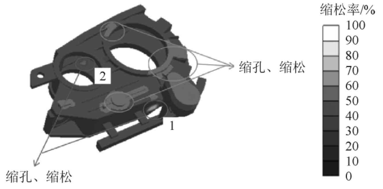
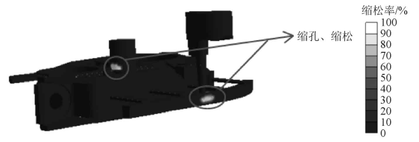
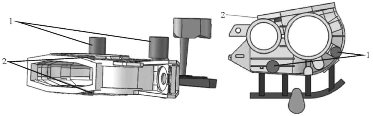
By analyzing the defects of the original process scheme in combination with figure 1, it can be seen that the shrinkage porosity and shrinkage cavity defects at position 1 are due to the too short ingate, the too fast speed of liquid metal flowing into the mold cavity, and the thick wall thickness, which eventually leads to the slow cooling speed and the formation of shrinkage porosity and shrinkage cavity. Therefore, double the length of the ingate to improve the defects here; Due to the same thick wall thickness at two places, in view of the shrinkage porosity and shrinkage cavity, add cold iron at the hot joint to increase the solidification speed of the thick part; In view of the multiple shrinkage cavities in the sand casting, risers are set at the top boss of the sand casting. The final optimization scheme is shown in Figure 2.
2. Simulation analysis of optimization scheme
Fig. 3 is the schematic diagram of mold filling process and solidification process of the optimization scheme. As can be seen from Fig. 3a, it takes 21.84s from liquid metal entering the cavity to filling, which is basically consistent with the simulation results of the original scheme. The whole mold filling process is relatively stable without splashing and air entrainment of liquid metal. The mold is filled layer by layer, and the liquid metal is finally filled into the riser, so the scum in the liquid metal will eventually be concentrated in the riser; As can be seen from Fig. 3b, compared with the original scheme, the solidification time is basically the same, but due to the addition of cold iron, the solidification of sand castings basically presents the sequence of solidification from left to right, and the length of inner sprue is increased, which plays a certain role in feeding sand castings. Two risers are set at the top of sand mold casting. During solidification, the liquid metal near the cold iron is cooled first, the liquid metal in the mold cavity is fed from left to right, and the riser is finally solidified, which plays a good feeding role.
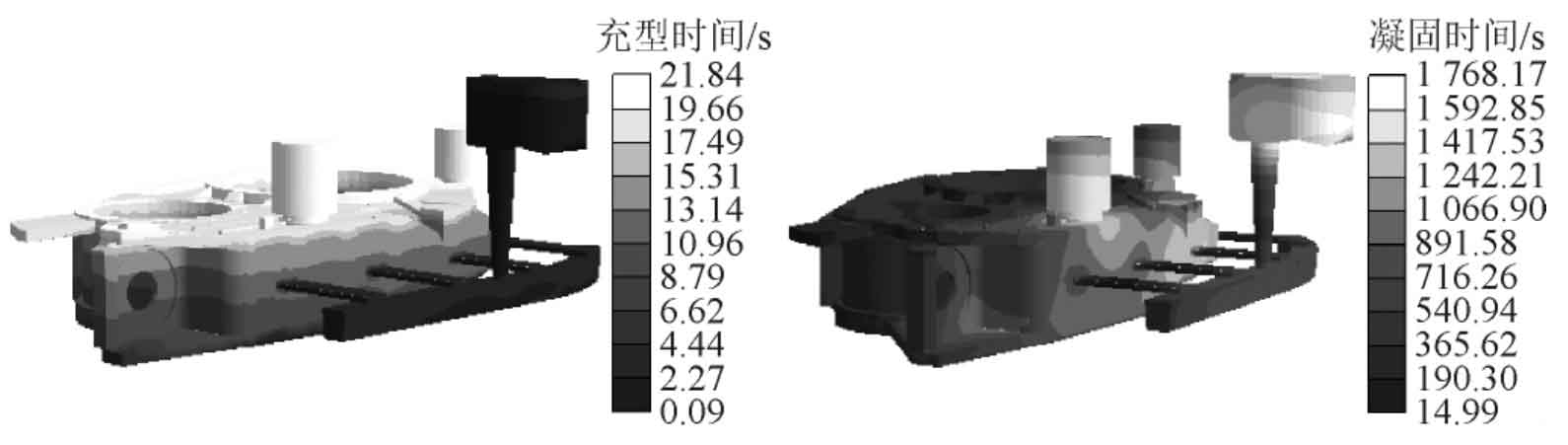
Figure 4 shows the defect analysis of the optimization scheme. It can be seen that many defects in the original scheme have been eliminated, and the optimized process scheme has only two shrinkage defects on the riser and runner.