
The landscape of component manufacturing is undergoing a profound transformation, driven by the rapid evolution of additive manufacturing (AM) technologies. While initially the domain of aerospace and high-end engineering, these techniques are now permeating the automotive industry. Their application spans from rapid prototyping of complex assemblies like engine blocks and motor housings to the production of small-batch, topology-optimized parts with intricate internal channels that defy conventional manufacturing, and even to the fabrication of conformal cooling inserts for casting and forming dies to enhance production efficiency. Within this spectrum, two AM-enabled processes for aluminum alloys have garnered significant attention: direct metal fabrication via Selective Laser Melting (SLM) and the indirect route of using binder jetting (3D Printing, 3D-P) to produce sand molds for casting. This article presents a detailed, first-person investigation into the microstructure and mechanical properties of AISi10Mg alloy components produced by these two distinct routes. The AISi10Mg alloy, a workhorse Al-Si-Mg series near-eutectic alloy, is chosen for its excellent castability, good strength-to-weight ratio, low thermal expansion, and high thermal conductivity, making it a prime candidate for both traditional and advanced manufacturing in automotive applications.
The fundamental premise of this comparison lies in the radically different thermal histories imparted by each process. SLM is a powder-bed fusion technique where a high-energy laser beam selectively melts thin layers of metal powder, layer by layer. This results in extremely high localized heating and cooling rates, often exceeding $$10^3 – 10^6\ K/s$$. The rapid solidification refines the microstructure, can create metastable phases, and introduces significant residual stresses. In contrast, the process for creating sand casting products via 3D-P involves using a binder-jetting printer to fabricate a sand mold directly from a digital model. Molten AISi10Mg is then poured into this mold, following a solidification regime characteristic of traditional sand casting, with cooling rates orders of magnitude slower (typically $$10^{-1} – 10^1\ K/s$$). This work systematically explores how these divergent process physics manifest in the final alloy’s grain structure, phase morphology, tensile strength, ductility, and fracture behavior.
| Feature | Selective Laser Melting (SLM) | 3D-P Sand Mold Casting |
|---|---|---|
| Process Type | Direct Metal Additive Manufacturing | Indirect Additive Manufacturing (Mold Fabrication) |
| Material Form | Gas-atomized powder (20-63 µm) | Molten alloy poured into 3D-printed sand mold |
| Energy Input | Focused laser beam (High power density) | Bulk heating and pouring (Low power density) |
| Cooling Rate | Very High ($$10^3 – 10^6\ K/s$$) | Low ($$10^{-1} – 10^1\ K/s$$) |
| Primary Thermal Effect | Ultra-fast solidification, Marangoni convection in melt pool | Slow, directional solidification governed by mold geometry |
| Key Advantage | Geometric freedom, fine microstructure, high as-built strength | Ability to produce large, complex sand casting products without pattern tooling |
| Key Challenge | Residual stress, anisotropy, powder handling | Internal defects (gas porosity, shrinkage), coarse microstructure |
Microstructural Evolution: From Fine Cells to Coarse Dendrites
My examination begins with the microstructure, as it is the primary determinant of mechanical properties. For the SLM-processed AISi10Mg samples in their as-built state, the microstructure is characterized by a fine cellular-dendritic structure of α-Al supersaturated with Si, surrounded by a continuous or semi-continuous network of ultrafine eutectic Si. This Si network is partially or completely fibrous/nanometric due to the extreme non-equilibrium solidification, which severely restricts Si diffusion and growth. After subjecting the samples to a stress-relief annealing at 300°C for 2 hours, a critical microstructural transformation occurs. The fine cellular structure remains, but the eutectic Si undergoes significant spheroidization and coarsening. The Si particles migrate from the cell boundaries and agglomerate into discrete, equiaxed particles. The driving force for this is the reduction of interfacial energy, described by the Ostwald ripening phenomenon, where the growth rate of a particle is inversely proportional to its radius. The process can be simplified as the diffusion-controlled growth:
$$
\overline{r}^3 – \overline{r_0}^3 = \frac{8\gamma C_{\infty}D V_m}{9RT}t
$$
where $\overline{r}$ is the average particle radius at time $t$, $\overline{r_0}$ is the initial radius, $\gamma$ is the interfacial energy, $C_{\infty}$ is the solubility in the matrix, $D$ is the diffusion coefficient, $V_m$ is the molar volume, $R$ is the gas constant, and $T$ is the annealing temperature. This spheroidization is crucial for enhancing ductility.
In stark contrast, the microstructure of the sand casting products (after T6 heat treatment: solutionizing at ~535°C followed by artificial aging) reveals a classic cast morphology. The primary α-Al phase exhibits a coarse dendritic structure, with secondary dendrite arm spacing (SDAS) significantly larger than the cell size in SLM material. The eutectic Si, which was modified during melting, appears as coarse, fragmented lamellae or needle-like particles situated in the interdendritic regions. Even after solution treatment, which aims to dissolve and homogenize secondary phases, remnants of this coarse Si morphology often persist, and the Mg₂Si hardening precipitates formed during aging are distributed within the α-Al grains. The stark difference in scale is a direct consequence of the cooling rate difference, often related by an equation of the form:
$$
\lambda = A (\dot{T})^{-n}
$$
where $\lambda$ is the dendrite arm spacing or cell size, $\dot{T}$ is the cooling rate, and $A$ and $n$ are material constants. The slower cooling in sand casting leads to a much larger $\lambda$, inherently limiting the strength potential compared to the refined SLM structure.
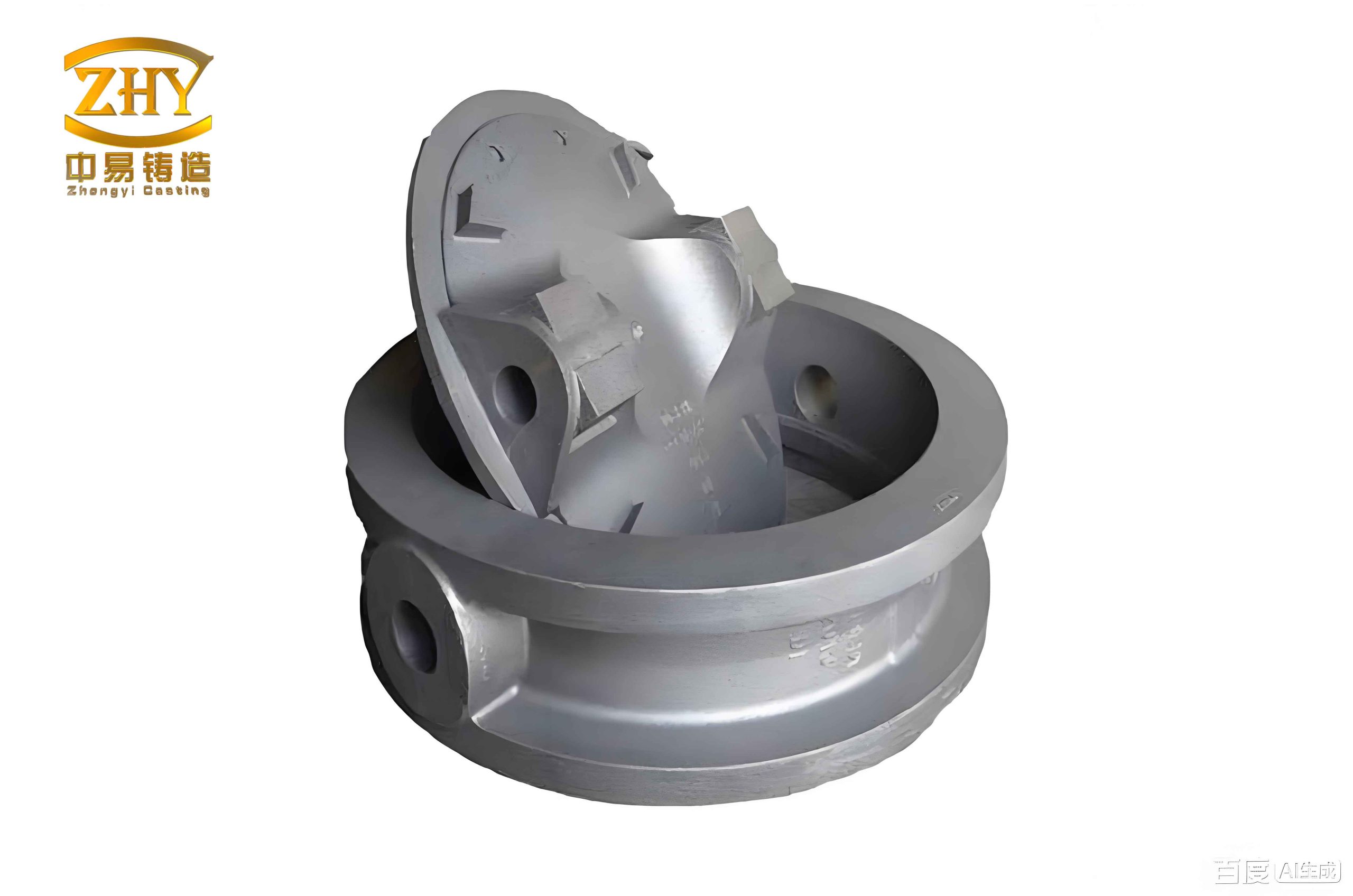
Anisotropy and Mechanical Performance: Data-Driven Comparison
A pivotal finding from my analysis of the SLM samples is the pronounced anisotropy in mechanical properties relative to the build direction. This is an intrinsic feature of layer-wise AM processes, influenced by factors like melt pool geometry, inter-layer bonding, and the directionality of microstructural features and defects. Testing samples printed at 0°, 45°, and 90° to the build plate revealed a systematic trend. The yield strength ($\sigma_y$) and ultimate tensile strength (UTS) progressively increased as the loading direction aligned more closely with the layer planes (i.e., from 90° to 0°). The anisotropy can be partially modeled by considering the orientation of potential weak interfaces, such as lack-of-fusion pores or oxidized layers, relative to the applied stress tensor. The strength $\sigma(\theta)$ at an angle $\theta$ to the layer plane might be approximated by a simple shear-lag or mixed-mode criterion:
$$
\sigma(\theta) = \left[ \frac{\cos^2\theta}{\sigma_{\parallel}^2} + \frac{\sin^2\theta}{\sigma_{\perp}^2} \right]^{-1/2}
$$
where $\sigma_{\parallel}$ and $\sigma_{\perp}$ are the strengths parallel and perpendicular to the layers, respectively. In my tests, the difference between the 0° and 90° directions was approximately 40-50 MPa in the as-built condition. However, the 300°C/2h stress relief anneal effectively homogenized these properties. The heat treatment relieves the high residual stresses locked in from rapid cooling and promotes microstructural uniformity (like Si spheroidization), thereby mitigating the directionality. The post-anneal properties showed remarkable consistency across all build orientations.
The tensile performance of the 3D-P sand-cast samples was markedly different and displayed higher variability, which is characteristic of sand casting products. Defects inherent to the process—such as microshrinkage porosity, gas entrapment from binder decomposition, and sand inclusions—act as potent stress concentrators and failure initiation sites. The Weibull modulus, a measure of strength reliability, is typically lower for cast materials compared to wrought or finely processed AM materials. While T6 heat treatment significantly improved the strength of the cast alloy by facilitating precipitation hardening ($\beta”$ Mg₂Si precipitates), it often came at the expense of ductility. The coarse Si particles and pre-existing voids provide easy paths for crack propagation.
| Process & Condition | Yield Strength (MPa) | Ultimate Tensile Strength (MPa) | Elongation at Break (%) | Hardness (HB) | Key Microstructural Features |
|---|---|---|---|---|---|
| SLM (As-Built) | 220 – 280 (Anisotropic) | 320 – 380 | 3 – 6 | 115 – 130 | Fine α-Al cells, fibrous Si network, high residual stress |
| SLM (300°C/2h Annealed) | 230 – 250 (Isotropic) | 310 – 330 | 10 – 14 | 105 – 115 | Spheroidized Si particles, stress-relieved, fine cells remain |
| 3D-P Sand Cast (As-Cast) | 110 – 150 | 180 – 220 | 2 – 4 | 60 – 75 | Coarse α-Al dendrites, lamellar/modified Si, porosity |
| 3D-P Sand Cast (T6 Temper) | 200 – 230 | 240 – 280 | 1 – 3 | 90 – 105 | Coarse dendrites, fragmented Si, age-hardened (Mg₂Si) |
| Traditional Die Casting | 140 – 180 | 240 – 300 | 1 – 3 | 80 – 95 | Very fine skin, porous core, externally solidified crystals |
Fractography and Failure Mechanisms
The fracture surfaces tell a compelling story of the differing failure modes. The fracture surface of the annealed SLM tensile specimens exhibited a mixed-mode morphology. Large areas showed fine, shallow dimples, indicative of microvoid coalescence—a ductile failure mechanism. This correlates with the good post-anneal ductility ($>$10%). Intermingled with these were smoother, faceted regions corresponding to the fine cell boundaries or areas where crack propagation occurred along the interfaces of the spheroidized Si particles. The overall energy absorption during fracture is higher than in the as-built state due to the enhanced plasticity from the softened matrix and rounded Si particles.
Conversely, the fracture surfaces of the T6-treated sand casting products were predominantly brittle. They displayed features like cleavage facets, river patterns, and isolated, large dimples associated with the decohesion of coarse Si particles or shrinkage pores. The crack path frequently followed the interdendritic regions, where the brittle Si phases and potential casting defects are concentrated. The limited plastic deformation observed is consistent with the low elongation values. The fracture toughness ($K_{IC}$) of such cast structures is generally lower than that of the fine, homogeneous SLM structure after annealing, as described by models linking toughness to microstructural scale:
$$
K_{IC} \propto \sigma_y \sqrt{\lambda}
$$
where a finer microstructure ($\lambda$) can, up to a point, improve toughness for a given yield strength ($\sigma_y$).
Process Parameters, Optimization, and Post-Processing
The performance of SLM AISi10Mg is highly sensitive to a complex interplay of laser parameters. Key variables include laser power ($P$), scan speed ($v$), hatch spacing ($h$), and layer thickness ($t$). The volumetric energy density ($E_v$), often used as a preliminary guideline, is given by:
$$
E_v = \frac{P}{v \cdot h \cdot t}
$$
However, $E_v$ is an oversimplification; optimal parameters must balance sufficient melting to achieve dense parts (minimizing porosity $< 0.5\%$) against excessive energy input that can cause keyhole porosity, balling, or increased residual stress. My work involved parameter optimization to achieve a stable melt pool. For the powder used (20-63 µm), a combination of moderate power and high scan speed proved effective in generating a fine, dense microstructure.
For 3D-P sand casting, the process parameters shift to the mold-making and pouring stages. The sand properties (grain size, shape), binder type and concentration, and printing resolution determine mold strength, permeability, and surface finish. The pouring temperature of the AISi10Mg melt, the use of chills to control solidification direction, and the gating/risering design (simulated via software) are critical to reduce shrinkage and gas porosity in the final sand casting products. Post-casting, the T6 heat treatment cycle is vital: solutionizing must be long enough to dissolve Mg and Si into the Al matrix without causing incipient melting of the eutectic, and aging must be optimized to precipitate the maximum number of fine $\beta”$ hardening phase.
| Process | Critical Parameter | Typical Range (This Work) | Primary Influence |
|---|---|---|---|
| SLM | Laser Power | 350 – 400 W | Melt pool depth, penetration |
| Scan Speed | 1200 – 1500 mm/s | Cooling rate, melt pool stability | |
| Hatch Spacing | 0.10 – 0.18 mm | Overlap, surface roughness, density | |
| Layer Thickness | 0.03 – 0.05 mm | Resolution, build rate, remelting | |
| 3D-P Sand Casting | Sand Grain Size | 100 – 140 mesh | Mold surface finish, permeability |
| Binder Saturation | Optimized for strength | Green strength, gas evolution | |
| Pouring Temperature | ~720°C | Fluidity, shrinkage characteristics | |
| Solution Treatment | ~535°C / 4-8 hours | Homogenization, dissolution of phases |
Discussion: Synergies, Applications, and Economic Considerations
The comparative data leads to a clear conclusion: SLM produces AISi10Mg components with superior and more consistent mechanical properties, especially after a simple stress-relief anneal. Its strengths are the fine, isotropic microstructure, high as-built strength, and excellent dimensional accuracy for complex geometries. The primary weaknesses are the build volume limitations, high initial machine and powder cost, and the need for support structures and post-processing (like base plate removal and surface finishing).
The value proposition for 3D-P sand casting lies not in outperforming SLM mechanically, but in its unique manufacturing niche. It is unrivaled for producing very large, complex, single-piece or low-volume molds that would be impossible or prohibitively expensive to make with traditional pattern-making. This makes it ideal for prototyping large engine blocks, cylinder heads, or structural components, and for producing legacy or bespoke sand casting products in small quantities. Its mechanical properties are acceptable for many non-critical or static applications, especially after T6 treatment, and it benefits from the vast existing knowledge base of aluminum sand casting.
An emerging paradigm is the hybrid or complementary use of both technologies. For instance, an SLM-printed high-strength, conformally cooled insert could be placed into a 3D-printed sand mold to locally control solidification and improve the properties of a critical section in a large casting. The economic comparison is multifaceted. A simplified cost-per-volume model must account for:
- SLM: Machine amortization, powder cost ($/kg), build time (scan speed, packing density), post-processing labor, and support material.
- 3D-P Sand Casting: Printer amortization, sand and binder cost, mold printing time, melting and pouring operations, finishing (shot blasting, machining), and scrap rate due to defects.
The breakeven point for volume is a key determinant. SLM becomes more competitive for smaller, highly complex parts where machining from billet is expensive, or for integrated assemblies that reduce part count. 3D-P sand casting is more economical for larger parts, especially as the part size increases, where the cost of an equivalent SLM machine (with large build volume) escalates dramatically.
| Decision Factor | Favors SLM | Favors 3D-P Sand Casting |
|---|---|---|
| Mechanical Performance | High strength, good ductility, fatigue resistance required | Static loads, non-critical components, stiffness-driven design |
| Geometric Complexity | Internal channels, lattices, organic shapes, thin walls | Large, bulky shapes, complex external surfaces, large cores |
| Production Volume | Low to medium volume (1 – 10,000 units) | Very low volume (prototypes) or medium volume (with multiple molds) |
| Part Size | Small to medium (within machine bed, typically < 500mm) | Very large (limited by furnace and handling, can be meters) |
| Lead Time | Fast for digital-to-part (hours/days for small parts) | Fast for mold, but includes casting and heat treatment cycle |
| Surface Finish | Requires post-machining for smooth surfaces | As-cast surface typical of sand casting products, requires machining for sealing faces |
| Material Efficiency | High (near-net-shape, unused powder recyclable) | Lower (gating/risering scrap, but metal is recyclable) |
Conclusion and Future Outlook
My investigation demonstrates that the choice between laser additive manufacturing (SLM) and binder-jetted sand mold casting for AISi10Mg is not a matter of one being universally better than the other. It is a strategic decision based on application requirements. SLM delivers components with refined, isotropic microstructures and superior mechanical properties, making it suitable for high-performance, weight-sensitive, and complex functional parts. The 300°C/2h anneal is a simple yet highly effective step to eliminate anisotropy and enhance ductility, making the material highly reliable.
3D-P sand casting, on the other hand, is a transformative tool for the foundry industry, breaking the constraints of traditional pattern making. It excels at producing geometrically complex molds for large or low-volume sand casting products, offering unparalleled design freedom at the tooling stage. While the resulting castings exhibit the typical coarse microstructure and property variability of sand castings, they are entirely fit-for-purpose for a wide range of applications, particularly when enhanced by standard T6 heat treatment.
The future lies in the intelligent application of each technology within a digital manufacturing ecosystem. Advances in multi-laser SLM systems will increase build rates and reduce costs for medium-volume production. Improvements in sand binder chemistry and printing resolution will enhance the surface finish and dimensional accuracy of castings. Furthermore, the integration of real-time process monitoring, machine learning for parameter optimization, and multi-physics simulation linking process parameters to final properties will drive both technologies toward greater reliability and performance predictability. For engineers and designers, the understanding of these fundamental process-property relationships is essential for selecting the right tool to bring innovative aluminum components to life.