
In my research and development work, I have consistently encountered significant challenges in the production of new, complex tractor components such as engine blocks, cylinder heads, and chassis housings. These sand casting products are typically characterized by their large size, intricate geometries, and thin walls. The conventional approach, which relies on designing and fabricating complex metal molds (pattern equipment) for sand molding and core-making, presents a major bottleneck. This traditional method is often associated with long lead times, high upfront costs for tooling, significant energy consumption, and difficulties in controlling the final casting quality. For a manufacturer tasked with developing dozens of new cast parts annually, this “high-input, low-efficiency” model is unsustainable. It creates a critical need for a rapid, flexible, and cost-effective foundry methodology specifically for low-volume production and prototyping of complex sand casting products.
The Proposed Rapid, Mold-Less Sand Casting Workflow
To address these constraints, I have developed and refined an integrated process that bypasses traditional pattern making entirely. This methodology synergizes Computer-Aided Design (CAD), additive manufacturing, subtractive manufacturing, and conventional sand casting principles. The core philosophy is to directly fabricate the required sand molds and cores using digital data, then assemble and pour them to obtain the final casting. The complete workflow is systematized as follows:
- Digital Model Preparation & Casting Process Design: The process begins with a 3D CAD model of the desired tractor component. Features meant for post-casting machining (e.g., bolt holes, oil passages) are filled or supplemented with machining allowances. The model is then scaled to account for solidification shrinkage, a critical step defined by the alloy. For the common ferrous alloys used in tractors, the scaling factor is typically:
$$ SF = 1 + \alpha $$
where \( \alpha \) is the linear shrinkage allowance (e.g., 0.01 for cast iron, 0.02 for cast steel). Following this, the gating and risering system is designed digitally to ensure proper filling, feeding, and soundness of the casting. - Virtual Casting Simulation (CAE): The designed process is virtually validated using casting simulation software. This step predicts potential defects like porosity, cold shuts, or misruns, allowing for iterative optimization of the gating system and the placement of chills before any physical fabrication begins.
- Mold & Core Partitioning (Digital Tooling): Instead of designing physical patterns, the complete mold assembly is digitally decomposed into individual sand cores and mold halves. This “digital tooling” step is guided by principles of manufacturability for the subsequent additive/subtractive steps and ease of assembly. Complex internal cores may be further split into “loose blocks” to facilitate fabrication.
- Direct Fabrication of Molds/Cores: The partitioned digital models are used to drive fabrication equipment:
- Additive Manufacturing (AM): For intricate, thin-walled cores.
- Subtractive Manufacturing (SM): For larger, geometrically simpler mold halves and cores.
- Assembly, Pouring, and Finishing: The fabricated sand components are assembled using alignment features designed in step 3, bonded, coated, dried, and then poured with molten metal. After cooling, the casting is knocked out, cleaned, and undergoes finishing operations.
| Process Stage | Key Action | Typical Parameters/Choices |
|---|---|---|
| Model Preparation | Scaling for Shrinkage | Cast Iron: 1.0-1.5%, Cast Steel: 2.0-2.5% |
| Process Design | Gating System Design | Horizontal pouring for iron; choke area calculated via: $$ A_{choke} = \frac{W}{\rho \cdot t \cdot C_d \sqrt{2gH}} $$ where \(W\) is casting weight, \(\rho\) is metal density, \(t\) is pour time, \(C_d\) is discharge coefficient, \(g\) is gravity, \(H\) is effective sprue height. |
| Mold Partitioning | Core/Mold Division | Goal: Minimize number of parts. Design alignment features (pins/sockets). |
| Additive Fabrication | Laser Sintering of Coated Sand | Layer thickness: 0.3 mm; Pre-heat temp: 70-80°C; Post-cure: ~200°C. |
| Subtractive Fabrication | CNC Milling of Sand Blanks | Tool path strategy: Roughing (Φ16 mm) → Finishing (Φ8 mm/B6 mm ball). Feed rate: 2 mm (flat end), 0.2 mm (ball end). |
In-Depth Process Design and Partitioning Strategy
The success of this rapid method hinges on meticulous digital process planning. For a complex housing, the design process is multi-faceted. After the gating system is laid out virtually, the mold is “reverse-engineered” from the part geometry. The partitioning strategy aims to create the fewest number of core boxes and mold pieces possible to simplify assembly. For instance, a transmission housing might be split into a top mold half, a bottom mold half, and a large central core. Internal undercuts or radial features within this central core that are inaccessible to milling tools are designed as separate, loose pieces.
Material selection for these digitally fabricated mold components is critical and varies based on function and geometry:
- Large Mold Halves & Thick Cores: Often made from sodium silicate-bonded sand or furan no-bake sand, chosen for their good strength and lower cost when used in bulk for subtractive manufacturing.
- Thin-Walled, Complex Cores: Often made from phenolic or furan-coated sands (e.g., “pearl sand”) processed via additive manufacturing, as they offer high strength-to-thickness ratios and excellent surface finish.
A crucial design element often overlooked in traditional methods but easily incorporated in the digital model is the internal venting of cores. For complex cores like a cylinder head water jacket, internal vent channels can be digitally sculpted to provide an escape path for gases generated during pouring, significantly reducing the risk of blows and porosity in the final casting. Furthermore, all partitioned pieces must include precision alignment features, such as integrally designed pins and sockets, to ensure accurate core assembly without the need for external fixtures.
Core Fabrication via Additive Manufacturing
For the most geometrically complex cores within tractor sand casting products, additive manufacturing, specifically Selective Laser Sintering (SLS), is the preferred method. This process builds the core layer-by-layer by using a laser to selectively fuse grains of pre-coated resin sand.
The workflow is highly digital and automated. The core model in STL format is imported into the SLS machine. For geometries with unstable bases or large overhangs, digital support structures or a base plate are added. The process parameters are finely tuned; for a typical phenolic-coated sand, the pre-heating temperature of the powder bed is maintained between 75-80°C for critical layers and around 70°C for others, with a laser scan spacing of approximately 0.15 mm. After the build is complete, the “green” core is carefully excavated from the loose powder bed. It possesses initial but fragile strength. To achieve the necessary handling and casting strength, the core undergoes a post-processing infiltration and curing cycle, often involving exposure to temperatures around 200°C. While this method offers unparalleled geometric freedom and excellent surface quality, its relatively slow build speed and high material cost make it ideal only for the most intricate sub-components.
Mold and Core Fabrication via Subtractive Manufacturing
To efficiently produce the larger mold halves and major cores, subtractive manufacturing via CNC milling is employed. This method is exceptionally cost-effective and fast for these less complex volumes. The process begins not with a block of metal, but with a pre-cured block of bonded sand—the “green blank.” These blanks are simply produced by mixing sand with the chosen binder (e.g., sodium silicate, furan resin) and compacting it in a simple, reusable box frame.
The digital workflow involves generating precise toolpaths from the 3D mold model. A common strategy is a three-stage milling operation: a roughing pass with a large flat-end mill (e.g., 16 mm) to remove the bulk of material, followed by a rest-milling operation with a medium tool (e.g., 8 mm) to clear remaining corners, and finally a finishing pass with a ball-nose end mill (e.g., 6 mm) to achieve the final surface geometry and accurate contours. The machined sand components exhibit excellent dimensional accuracy, typically within ±0.5 mm, which is fully acceptable for sand casting purposes. This method’s efficiency and lower cost perfectly complement the capabilities of additive manufacturing within the integrated rapid casting workflow.
| Aspect | Additive Manufacturing (SLS of Coated Sand) | Subtractive Manufacturing (CNC Milling of Sand) |
|---|---|---|
| Best Suited For | Extremely complex, thin-walled cores with internal passages. | Large mold halves, cores with simpler overall geometry. |
| Key Advantage | Unmatched geometric freedom; no toolpath accessibility issues. | High fabrication speed; low cost per volume of material. |
| Primary Limitation | Slower build rate; higher material and machine cost. | Geometric constraints due to tool access (undercuts). |
| Typical Material | Phenolic or Furan Pre-coated Sand (Pearl Sand). | Sodium Silicate Sand, Furan No-Bake Sand. |
| Surface Finish & Accuracy | Very Good, limited by layer thickness and particle size. | Excellent, directly related to CNC machine precision and tool stepover. |
| Role in Workflow | Fabrication of “problem geometry” cores. | Fabrication of the bulk of the mold assembly. |
Assembly, Casting, and Validation
The final physical phase involves assembling the digitally born sand components. The cores and mold halves are bonded using core assembly adhesives, with small loose blocks potentially secured by steel pins. Before final closing, the mold is inspected, repaired if necessary, and coated with a refractory wash. After drying, the mold is closed, weighted down, and poured. Following solidification and cooling, the casting is shaken out, the feeding and gating systems are removed, and the part is cleaned via shot blasting.
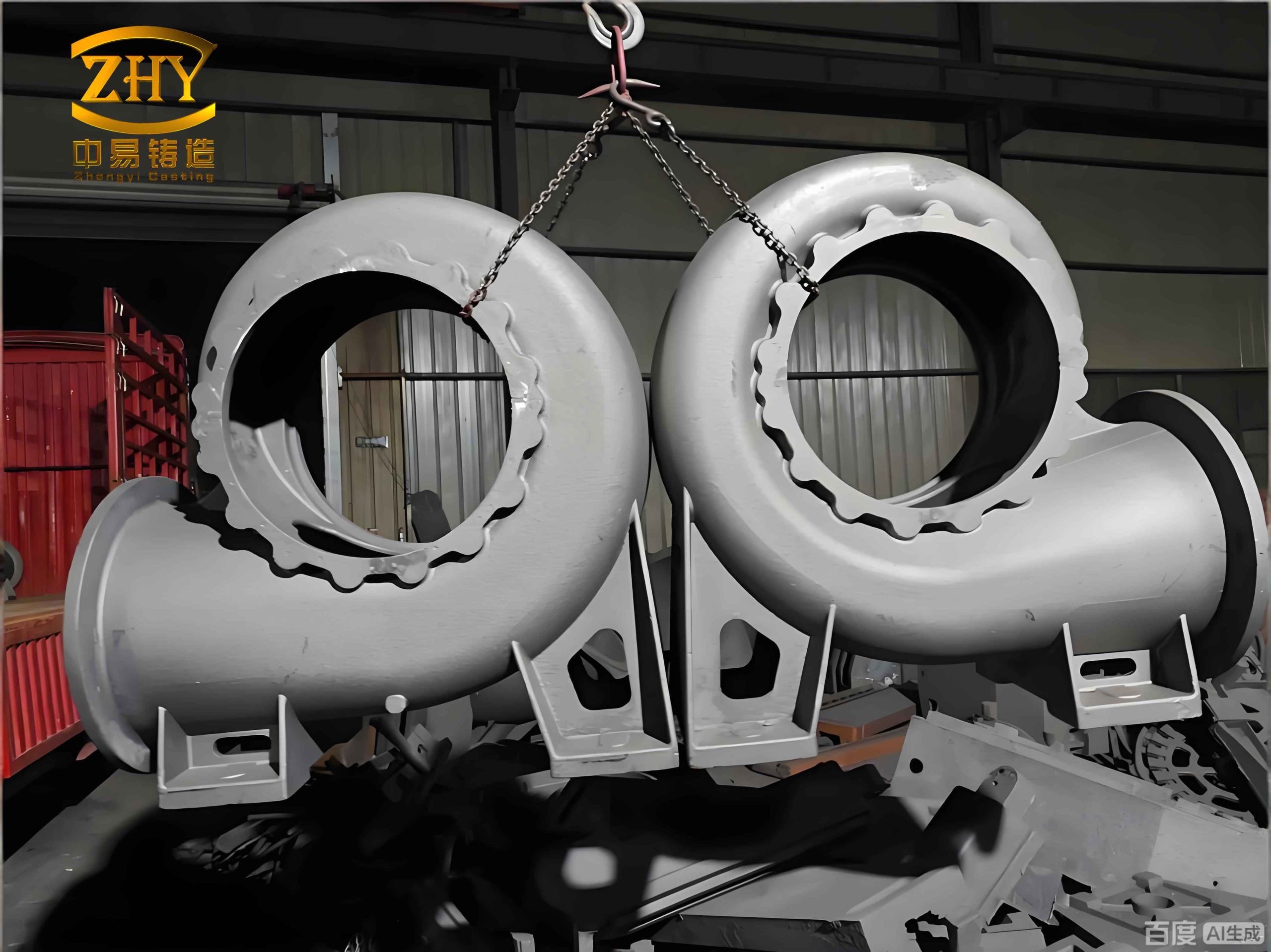
The impact of this integrated approach on development metrics is profound. For a complex tractor transmission housing, the total lead time for producing the first prototype casting—encompassing all digital design, simulation, and physical mold/core fabrication—can be reduced to approximately 120 hours. In stark contrast, the conventional pattern design and manufacturing route routinely consumes three months or more. Financially, the savings are immediate and substantial, as the entire cost category associated with hard pattern tooling (often tens of thousands of dollars) is eliminated for the prototype phase. This makes the mold-less method exceptionally economical for low-volume production and design validation of new, complex sand casting products.
Conclusion and Advantages
The integration of additive and subtractive digital manufacturing techniques into the sand casting workflow presents a transformative methodology for developing complex tractor components. This mold-less approach offers decisive advantages:
- Dramatically Reduced Lead Time and Cost: It completely bypasses the lengthy and expensive pattern-making stage, enabling rapid iteration and validation of new designs for sand casting products.
- Enhanced Design Flexibility and Accuracy: Changes to the casting design can be made directly in the CAD model and almost instantly reflected in the next set of molds/cores, with high dimensional accuracy ensured by digital fabrication.
- Synergistic Use of Technologies: By strategically applying additive manufacturing for complex cores and subtractive manufacturing for larger elements, the process optimizes for both geometric capability and production efficiency.
- Resource Efficiency: The method aligns with green manufacturing principles by reducing waste associated with pattern making and enabling precise use of sand materials, moving towards a resource-saving, precision-forming paradigm.
This digital foundry approach effectively addresses the historical “high-input, low-efficiency” problem in prototyping complex castings. It provides a viable, agile pathway for accelerating innovation and product development in the agricultural machinery sector and beyond, fundamentally changing how we approach the initial production of complex sand casting products.