
In the modern manufacturing landscape, the production of sand casting products has undergone a transformative shift toward digital and patternless methods. As a researcher deeply involved in this field, I have observed that digital casting technology offers significant advantages, including reduced pollution, shorter production cycles, and lower costs. This is particularly crucial for complex and thin-walled sand casting products, which increasingly rely on five-axis linkage high-speed machining for sand mold forming. The ability to achieve precise and efficient molding directly impacts the quality and performance of final sand casting products. In this article, I will delve into the kinematics modeling, speed control mechanisms, and experimental validation of five-axis linkage forming for digital sand casting products, emphasizing the importance of high-speed control strategies to enhance productivity.
The core of five-axis linkage machining lies in the Rotation Tool Center Point (RTCP) functionality, which ensures the tool tip remains on the programmed trajectory despite rotational movements. For sand casting products, this is essential to maintain accuracy in complex mold geometries. I derive the kinematic model for a B-C double-swivel head structure, commonly used in sand mold forming due to its suitability for large-sized molds. The coordinate systems include the workpiece coordinate system $O_MX_MY_MZ_M$, the tool coordinate system $O_TX_TY_TZ_T$, and the rotary coordinate system $O_RX_RY_RZ_R$. The transformation matrices for B-axis and C-axis rotations are given by:
$$ R_B = \begin{bmatrix} \cos B & 0 & \sin B \\ 0 & 1 & 0 \\ -\sin B & 0 & \cos B \end{bmatrix}, \quad R_C = \begin{bmatrix} \cos C & -\sin C & 0 \\ \sin C & \cos C & 0 \\ 0 & 0 & 1 \end{bmatrix} $$
The tool tip position change due to rotation is calculated as $\Delta P = R_B \cdot R_C \cdot T_L + M_T$, where $T_L = [0, 0, -L]^T$ and $M_T = [0, 0, L]^T$, with $L$ being the swing length. To maintain the tool tip position, the linear axis coordinates $P = [P_X, P_Y, P_Z]^T$ are adjusted as follows:
$$ \begin{bmatrix} P_X \\ P_Y \\ P_Z \end{bmatrix} = \begin{bmatrix} P_{MX} + L \sin B \cos C \\ P_{MY} + L \sin B \sin C \\ P_{MZ} + L \cos B – L \end{bmatrix} $$
This inverse kinematics solution enables real-time RTCP compensation, critical for achieving high precision in sand casting products. The forward kinematics, used to verify tool tip positions, is derived as:
$$ \begin{bmatrix} P_{MX} \\ P_{MY} \\ P_{MZ} \end{bmatrix} = \begin{bmatrix} P_X – L \sin B \cos C \\ P_Y – L \sin B \sin C \\ P_Z – L \cos B + L \end{bmatrix} $$
Implementing these equations in an open control system, such as a Programmable Multi-Axes Controller (PMAC), allows for cyclic execution at intervals of 1–10 ms, ensuring smooth five-axis linkage for sand mold forming. This approach minimizes errors and enhances the surface quality of sand casting products, which is vital for reducing post-processing needs.
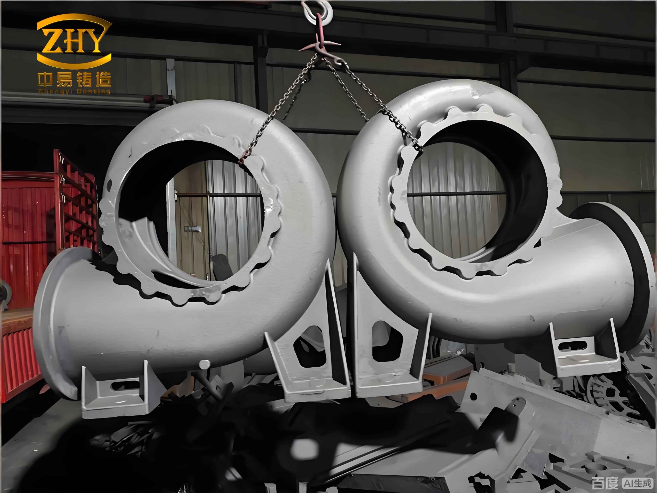
High-speed forming of sand casting products, however, introduces challenges related to speed fluctuations. In five-axis linkage machining, the vector speed is computed based on programmed coordinates, but RTCP compensation causes linear axis speeds to exceed programmed limits, especially with long tool lengths. This can lead to vibrations, equipment alarms, and defects in fragile sand molds, compromising the integrity of sand casting products. The time interval $t$ between command points is given by:
$$ t = \frac{\sqrt{\mu_X^2 \Delta P_{MX}^2 + \mu_Y^2 \Delta P_{MY}^2 + \mu_Z^2 \Delta P_{MZ}^2 + \mu_B^2 \Delta B^2 + \mu_C^2 \Delta C^2}}{F} $$
where $F$ is the programmed speed, and $\mu$ values convert units to pulses. The actual axis speeds $V_i$ are derived from RTCP inverse position increments:
$$ V_X = \frac{\mu_X \Delta P_X}{t}, \quad V_Y = \frac{\mu_Y \Delta P_Y}{t}, \quad V_Z = \frac{\mu_Z \Delta P_Z}{t}, \quad V_B = \frac{\mu_B \Delta B}{t}, \quad V_C = \frac{\mu_C \Delta C}{t} $$
The resulting actual vector speed $F_{act}$ often surpasses $F$, as shown by:
$$ F_{act} = F \times \sqrt{\frac{\mu_X^2 \Delta P_X^2 + \mu_Y^2 \Delta P_Y^2 + \mu_Z^2 \Delta P_Z^2 + \mu_B^2 \Delta B^2 + \mu_C^2 \Delta C^2}{\mu_X^2 \Delta P_{MX}^2 + \mu_Y^2 \Delta P_{MY}^2 + \mu_Z^2 \Delta P_{MZ}^2 + \mu_B^2 \Delta B^2 + \mu_C^2 \Delta C^2}} $$
To mitigate this, I propose a single-axis look-ahead control strategy. This method leverages the constraint that axis speed ratios are tied to position change ratios. For example, the speed ratio between X and Y axes is:
$$ \frac{V_X}{V_Y} = \frac{\mu_X \Delta P_X}{\mu_Y \Delta P_Y} $$
By setting a look-ahead threshold for one axis, the speeds of all five axes can be constrained without online computation for each. If X-axis is chosen, its speed limit $V_{Xthreshold}$ is calculated based on all axis limits:
$$ V_{Xthreshold} = \min \left( V_{Xlimit}, \frac{\mu_X \Delta P_X}{\mu_Y \Delta P_Y} V_{Ylimit}, \frac{\mu_X \Delta P_X}{\mu_Z \Delta P_Z} V_{Zlimit}, \frac{\mu_X \Delta P_X}{\mu_B \Delta B} V_{Blimit}, \frac{\mu_X \Delta P_X}{\mu_C \Delta C} V_{Climit} \right) $$
Similarly, thresholds for other axes can be derived, such as for Z-axis:
$$ V_{Zthreshold} = \min \left( V_{Zlimit}, \frac{\Delta P_Z}{\Delta P_X} V_{Xlimit}, \frac{\Delta P_Z}{\Delta P_Y} V_{Ylimit}, \frac{\Delta P_Z}{\Delta B} V_{Blimit}, \frac{\Delta P_Z}{\Delta C} V_{Climit} \right) $$
This single-axis look-ahead control dynamically adjusts acceleration and deceleration, ensuring speeds remain within safe limits for producing high-quality sand casting products. The number of look-ahead time segments $N$ is determined by:
$$ N = \frac{V_{threshold}^2}{2 A_{max} \cdot t_s} $$
where $A_{max}$ is the maximum acceleration and $t_s$ is the look-ahead servo period. This approach reduces computational load and enhances real-time performance, which is essential for the efficient manufacturing of sand casting products.
To validate these methods, I conducted experiments using a digital five-axis patternless casting precision forming machine. The machine parameters are summarized in the table below, highlighting its capability for sand casting products formation.
| Axis | Travel Range | Maximum Speed | Positioning Accuracy | Repeatability |
|---|---|---|---|---|
| X-axis | 1500 mm | 12000 mm/min | ±0.05 mm/300 mm | ±0.02 mm/300 mm |
| Y-axis | 2000 mm | 12000 mm/min | ±0.05 mm/300 mm | ±0.02 mm/300 mm |
| Z-axis | 700 mm | 12000 mm/min | ±0.05 mm/300 mm | ±0.02 mm/300 mm |
| C-axis | ±360° | 60 rpm | ±20″ | ±10″ |
| B-axis | ±90° | 30 rpm | ±20″ | ±10″ |
An impeller sand mold, representative of complex sand casting products, was machined with a tool diameter of 10 mm, swing length $L = 403.70$ mm, and programmed speed of F500. The RTCP forward and inverse kinematics were executed at a 5 ms cycle. The results showed that linear axis positions after RTCP compensation deviated significantly from programmed coordinates, as predicted by the kinematic model. The error between simulated and actual positions was within acceptable limits for sand casting products, with maximum errors of -0.036 mm in Y-direction and -0.034 mm in Z-direction. These errors correlated with axis accelerations, which peaked at high curvature regions of the toolpath.
Speed profiles during machining aligned with theoretical calculations. Without speed limits, linear axis speeds exceeded F500, reaching up to -7528 mm/min for Y-axis, causing vibrations. When programmed speed was increased to F2500, speed overruns worsened, with X-axis hitting -6440 mm/min, and errors increased to 0.072 mm in Y-direction and 0.077 mm in Z-direction. This underscores the necessity of speed control for sand casting products to prevent defects and equipment stress.
Implementing Z-axis look-ahead control with a threshold of $V_{Zthreshold} = 1234.1$ mm/min, based on axis limits of 2500 mm/min for linear axes and 1000°/min for rotary axes, effectively constrained all axis speeds. The machining time extended from 3.31 s to 11.4 s, but speeds remained within limits, and operation stabilized. The look-ahead error, influenced by trajectory curvature, was calculated as:
$$ E = \frac{V^2 T^2}{6R} $$
where $V$ is the vector speed, $T$ is the RTCP cycle time, and $R$ is the curvature radius. For the impeller sand mold, with $R$ ranging from 10.23 mm to 1778.96 mm and $T = 5$ ms, the maximum error was 0.00052 mm, negligible for sand casting products. This demonstrates that single-axis look-ahead control is a practical solution for high-speed five-axis linkage forming of sand casting products.
In summary, the RTCP kinematic model and single-axis look-ahead control strategy are effective for digital sand casting products manufacturing. The RTCP implementation minimizes tool tip errors, while look-ahead control prevents speed overruns, ensuring stable and efficient production. Future work should focus on trajectory smoothing for micro-line segments to further enhance the efficiency of sand casting products formation. The integration of these technologies into open control systems paves the way for advanced, green foundry practices, ultimately improving the quality and affordability of sand casting products in industries such as automotive, aerospace, and machinery.
The advancement of five-axis linkage forming for sand casting products not only reduces environmental impact but also accelerates prototyping and customization. As demand for complex sand casting products grows, these control methodologies will become increasingly vital. By leveraging real-time kinematics and adaptive speed planning, manufacturers can achieve higher precision and throughput, solidifying the role of digital casting in modern manufacturing. The continuous optimization of these techniques will drive innovation in sand casting products, enabling lighter, stronger, and more intricate designs that meet evolving market needs.