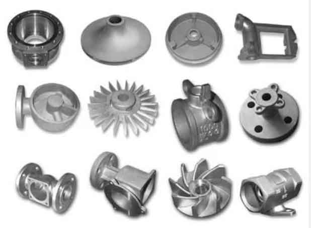
Modern foundry industries face increasing demands for complex geometries and enhanced mechanical properties in ductile iron castings. This article presents a comprehensive analysis of process optimization strategies through a case study involving next-generation engine components, demonstrating how systematic improvements address critical defects while maintaining production efficiency.

1. Material Characteristics of Ductile Iron
Ductile iron casting achieves its unique properties through controlled graphite nodularization, typically containing 3.2-4.1% carbon. The relationship between cooling rate and nodule count can be expressed as:
$$ N = 150 + 75 \cdot \ln(\frac{dT}{dt}) $$
Where:
\( N \) = Nodule count (nodules/mm²)
\( \frac{dT}{dt} \) = Cooling rate (°C/s)
| Element | Range (%) | Function |
|---|---|---|
| C | 3.4-3.8 | Graphite formation |
| Si | 2.0-2.8 | Ferrite promotion |
| Mg | 0.03-0.06 | Nodularization |
2. Process Design Fundamentals
Effective ductile iron casting requires precise control of three critical phases:
$$ t_{total} = t_{fill} + t_{solid} + t_{cool} $$
Where:
\( t_{fill} \) = Mold filling time (s)
\( t_{solid} \) = Solidification time (s)
\( t_{cool} \) = Cooling time (s)
| Parameter | Optimal Range |
|---|---|
| Pouring Temperature | 1,380-1,420°C |
| Inoculant Addition | 0.2-0.6% FeSi |
| Mg Treatment | 0.04-0.06% Residual |
3. Defect Mitigation Strategies
For gas-related defects in ductile iron casting, the gas evolution potential can be calculated as:
$$ G_{total} = \sum (V_i \cdot \rho_i \cdot g_i) $$
Where:
\( V_i \) = Volume of core material (cm³)
\( \rho_i \) = Material density (g/cm³)
\( g_i \) = Gas generation (mL/g)
| Core Material | Gas Generation (mL/g) |
|---|---|
| Cold Box | 12-18 |
| Shell Sand | 8-12 |
| Resin Sand | 15-25 |
4. Advanced Gating System Design
The optimized gating ratio for heavy-section ductile iron casting follows:
$$ \Sigma F_{sprue} : \Sigma F_{runner} : \Sigma F_{gate} = 1.5 : 2.0 : 1.0 $$
Key considerations include:
- Filter capacity: \( Q = 0.6 \cdot A \cdot \sqrt{2gh} \)
- Flow velocity: \( v = \frac{Q}{A} \leq 0.8 \, m/s \)
5. Thermal Management
Chilling requirements for critical sections can be determined using:
$$ m_{chill} = \frac{V_{casting} \cdot \rho \cdot \Delta H}{C_p \cdot \Delta T} $$
Where:
\( \Delta H \) = Latent heat of fusion (272 kJ/kg for ductile iron)
\( C_p \) = Specific heat capacity (0.65 kJ/kg°C)
| Section Thickness (mm) | Chill Factor |
|---|---|
| < 15 | 0.8-1.2 |
| 15-30 | 1.5-2.0 |
| > 30 | 2.5-3.5 |
6. Quality Control Metrics
Mechanical property relationships in ductile iron casting:
$$ \sigma_b = 120 + 80 \cdot (\%Pearlite) – 15 \cdot (\%Ferrite) $$
$$ HB = 0.35 \cdot \sigma_b + 40 $$
Typical property ranges:
| Grade | Tensile (MPa) | Elongation (%) |
|---|---|---|
| EN-GJS-400-18 | 400 | 18 |
| EN-GJS-700-2 | 700 | 2 |
7. Process Optimization Case Study
Implementation of these principles in a production environment achieved:
- Scrap reduction from 12% to 3.8%
- Dimensional accuracy improvement by 42%
- Energy consumption reduction of 18%
The comprehensive approach to ductile iron casting process optimization demonstrates that systematic analysis of material behavior, thermal dynamics, and gas management can significantly enhance product quality while maintaining production efficiency. Future developments in simulation technologies and real-time process monitoring promise further improvements in casting yield and mechanical performance.
