
The production of high-integrity, geometrically complex thin-walled shell castings represents a significant challenge in foundry engineering. My experience focuses on a critical component: a large, conical thin-walled shell casting with intricate internal and external features. This specific shell casting, a vital military component, is manufactured from ZL115 aluminum alloy via differential pressure casting. The primary challenges stem from its substantial size (747 mm length), variable wall thickness (nominally 6 mm), and the presence of pronounced thick sections like slanted wings and bosses adjacent to thin walls, with local wall thickness ratios as high as 5:1. This geometry inherently promotes shrinkage porosity and hot tearing, demanding a meticulously engineered process. The successful methodology hinges on the deliberate selection of a solidification principle, precise control of metal flow to manage superheat, and the intelligent application of pattern allowances. The lessons learned are broadly applicable to the manufacture of high-quality, demanding shell castings.
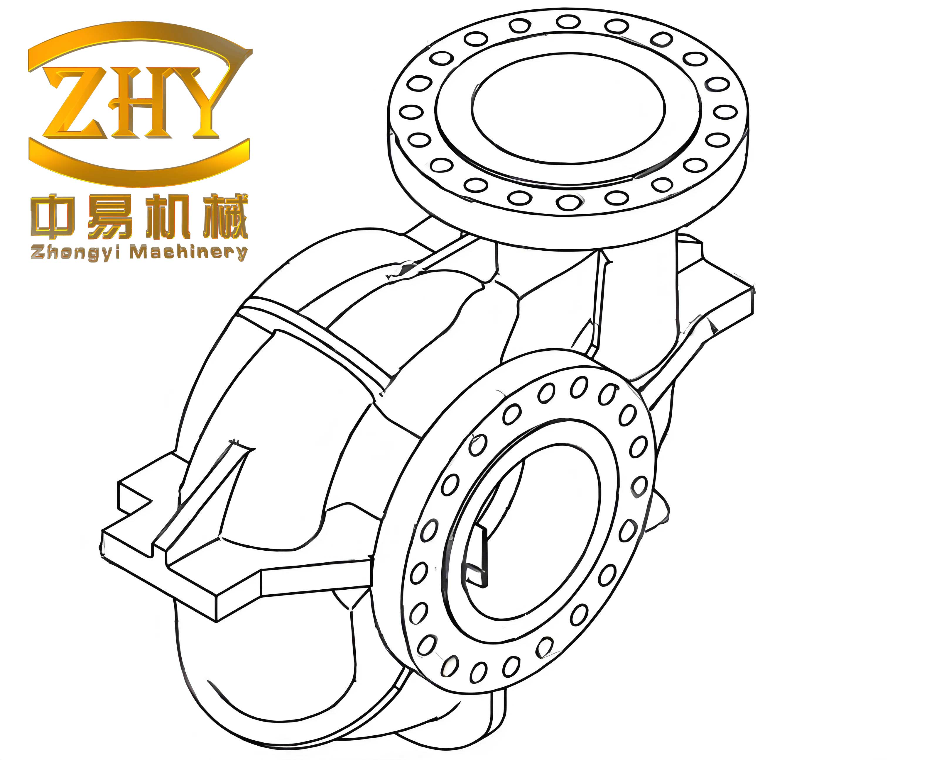
The technical requirements for these shell castings are stringent. Internal quality mandates 100% X-ray inspection, with a minimum acceptable quality level of D. Pressure tightness is critical, requiring the shell castings to withstand an internal gas pressure of 0.05 MPa for 15 minutes with minimal pressure drop and an external hydrostatic pressure of 0.5 MPa for 20 minutes without leakage. Dimensional accuracy is equally vital, with tight tolerances on the nominal wall thickness and on specific features like the angular relationship and width between two synchronizing boss features. Production utilizes dry sand molds with resin-bonded cores and medium-frequency induction melting.
The core of the process development was the strategic choice between directional and simultaneous solidification principles. The geometry of these shell castings—largely uniform thin walls interrupted by isolated heavy sections—dictates the approach. While the thin-walled body favors simultaneous solidification to avoid distortion, the heavy bosses and wings require directional solidification to ensure feed metal is available to compensate for shrinkage. The placement of the gating system and chill blocks is the primary tool for manipulating the thermal profile and solidification sequence of the shell castings.
Solidification Principle Selection and Experimental Validation
Two distinct gating and chilling strategies were devised and tested to determine the optimal approach for producing sound shell castings.
Strategy 1: Aiming for Simultaneous Solidification
This design attempted to equalize solidification times. Six vertical slot gates were placed, with two feeding from the bottom of the thin-wall section and four feeding up to two-thirds of the casting height. The heavy wing sections were positioned in the last-to-fill areas of the mold cavity. Extensive chill blocks were applied to three sides of each heavy wing to extract heat rapidly. The theoretical goal was to minimize the thermal gradient, allowing the thin walls to be fed by the gates and the chills to negate the geometric hot spots in the wings, thereby preventing shrinkage in the shell castings.
Strategy 2: Enforcing Directional Solidification
This design intentionally created a thermal gradient. Six vertical slot gates were again used, but their placement was pivotal. Two primary gates were positioned at the base of the heavy synchronizing bosses and wings, directly feeding these thick sections. Four secondary gates fed the thinner main body. Chill blocks were strategically used on the wings not to accelerate their cooling, but primarily to control the cooling direction and refine microstructure. The goal was to establish a clear solidification sequence: the thin walls solidify first, feeding towards the heavier sections, which are in turn fed by the metal in the primary gates. This creates a directional solidification path critical for the integrity of such shell castings.
The production results provided a clear verdict on the efficacy of each strategy for these specific shell castings. The performance comparison is summarized below:
| Strategy | Solidification Principle | Gating Focus | Castings Produced | Acceptable Castings | Yield Rate | Primary Defect |
|---|---|---|---|---|---|---|
| 1 | Simultaneous | Thin-wall body | 10 | 3 | 30% | Shrinkage in boss between wings |
| 2 | Directional | Thick sections (bosses/wings) | 20 | 14 | 70% | Significantly reduced |
The dramatic difference in yield underscores a key principle for complex shell castings: when significant isolated heavy sections exist within a thin-walled structure, attempting simultaneous solidification is often counterproductive. In Strategy 1, the thick wing sections, though chilled, were located in areas where they received metal that had already transferred its heat to the thin walls, putting them at a thermal disadvantage. More critically, the flow of a large volume of metal through the gate adjacent to the boss located between the two wings caused severe localized superheating. This superheat-induced thermal hotspot delayed solidification, creating a shrinkage cavity. Strategy 2 succeeded by directly feeding the heavy sections with gates, establishing a controlled thermal gradient and, crucially, avoiding the detrimental flow-induced superheat in critical junctions. For these conical shell castings, directional solidification proved to be the robust and necessary principle.
Analysis of Superheat-Induced Defects in Shell Castings
Superheat, defined as the temperature of the molten metal above its liquidus, is a critical but often overlooked factor in defect formation in shell castings. It is not merely a global pouring temperature parameter; localized superheating can be caused by the flow dynamics of the metal during mold filling. This is distinct from and additive to the geometric hot spot effect.
Superheat and Shrinkage Porosity Formation
In Strategy 1, the boss between the wings acted as a flow channel for metal destined for the upper parts of the casting. The continuous flow of hot metal through this restricted area transferred significant sensible heat to the mold, creating a sustained “physical hot spot.” The total solidification time ($t_f$) at a point can be considered a function of both geometric factors (wall thickness, $w$) and thermal history (initial mold temperature $T_m$, superheat $\Delta T_s$). A simplified expression highlights the influence:
$$ t_f \propto \frac{w^n}{\alpha} + k \cdot \Delta T_{s,local} $$
where $\alpha$ is the thermal diffusivity of the mold, $n$ is an exponent (often ~2), and $k$ is a factor relating to local heat transfer conditions. The localized superheat $\Delta T_{s,local}$ from metal flow directly increases the second term, extending $t_f$. When this physical delay coincides with a geometric hot spot (the boss itself), the combined effect can be expressed as an effective modulus ($M_{eff}$) that is larger than the geometric modulus ($M_g$):
$$ M_{eff} = M_g \cdot (1 + \beta \cdot \Delta T_{s,local}) $$
where $\beta$ is a coefficient. This extended solidification time at a point that is not favorably fed by a riser or gate inevitably leads to macroshrinkage in the shell castings.
Superheat and Hot Tear Initiation
Strategy 1 also led to occasional hot tears in the upper, thinner sections of the wings. The mechanism is again linked to flow-induced thermal profiles. As metal flowed past the base of the thin wing section to fill the mold above it, that junction became overheated. The surrounding areas (the thicker wing root and the cooler thin wall) solidified and began contracting while the overheated junction remained mushy or liquid. This established a strain field ($\epsilon$) across the weak, partially solidified material. A hot tear forms when the localized strain rate ($\dot{\epsilon}$) exceeds the material’s ability to accommodate it via viscous or plastic flow in the semi-solid state. The susceptibility can be modeled by considering the thermal gradient ($\nabla T$) and the coherency temperature range ($\Delta T_{coh}$):
$$ \dot{\epsilon} \propto \frac{\alpha \cdot \nabla T}{L} $$
where $L$ is a characteristic length. The low-strength, semi-solid material at the overheated junction cannot withstand the tensile stresses imposed by the contracting adjacent regions, leading to failure. This underscores that for delicate thin-walled shell castings, controlling metal flow to avoid creating such adverse thermal gradients is as important as the overall solidification pattern.
Pattern Allowance Strategy for Complex Shell Castings
The conical, constrained geometry of these shell castings necessitates a nuanced approach to pattern allowances, deviating from a single, uniform shrinkage factor. Different features shrink in different ways based on their geometry and the restraint offered by the mold and core. The target dimensional tolerances, particularly the ±0.6 mm on a 6 mm wall, demand this precision.
The internal cavity of the shell casting is fully cored. The axial (lengthwise) shrinkage is more restricted than the radial shrinkage due to the conical shape and the mechanical interference of the core along the length. Therefore, a differential allowance must be applied. Let $S_a$ represent the axial shrinkage factor and $S_r$ the radial shrinkage factor. Based on empirical results for this specific ZL115 alloy and mold/core configuration:
$$ S_a = 0.8\% $$
$$ S_r = 0.6\% $$
This means the pattern dimensions are scaled accordingly: $L_{pattern} = L_{casting} / (1 – S_a)$ and $D_{pattern} = D_{casting} / (1 – S_r)$.
For highly restrained features, the allowance approaches zero. The two U-shaped synchronizing bosses are a key example. Their 90° angular relationship and 60 mm width are considered “fully restrained” or “hindered contraction” dimensions. The mold and core physically prevent them from shrinking freely. For the angular dimension, no allowance is applied to the pattern. For the linear width dimension, a minimal allowance is used primarily to compensate for other factors like coating thickness ($t_{coat}$) which can effectively reduce the cavity size. The pattern width ($W_p$) is calculated as:
$$ W_p = W_c \cdot (1 + S_{hindered}) + 2t_{coat} $$
where $W_c$ is the casting width and $S_{hindered}$ is a very small factor (~0.5%). This meticulous approach is essential for achieving the tight tolerances required for precision shell castings.
| Feature Type | Description in Shell Castings | Contraction Nature | Recommended Allowance Factor | Key Consideration |
|---|---|---|---|---|
| Axial Length | Overall length of conical shell | Partially Hindered | 0.8% | Restraint from core and taper |
| Radial Diameter | Major diameters of the shell | Less Hindered | 0.6% | Core offers less radial restraint |
| U-shaped Boss Width | Width between synchronizing arms | Fully Hindered | 0.5% (or less) | Compensates for coating thickness; geometric restraint |
| Angular Relationship | 90° angle between features | Fully Hindered | 0.0% | Mold geometry completely restrains angular contraction |
Comprehensive Process Synthesis and Control Parameters
Integrating all findings, the optimized production process for high-integrity shell castings involves a system of controlled parameters. The differential pressure casting cycle itself is defined by key pressures and times: a pressurization rate ($dP/dt$), a maximum applied pressure ($P_{max}$), and a hold time at pressure ($t_{hold}$). These parameters ensure proper mold filling and interdendritic feeding. The thermal parameters are equally codified. The pouring temperature ($T_{pour}$) must be optimized to provide sufficient fluidity without excessive superheat. For ZL115, this typically lies in a narrow range above its liquidus temperature ($T_{liq}$):
$$ T_{pour} = T_{liq} + \Delta T_{opt} $$
where $\Delta T_{opt}$ is determined through practice (e.g., 30-50°C). The chill block design is quantified by its chilling modulus ($M_{chill}$), which should be proportionate to the modulus of the hot section it is intended to control:
$$ M_{chill} \geq C \cdot M_{casting-hot-spot} $$
where $C$ is a coefficient (often 0.5-2) depending on the desired effect (moderate directional control vs. aggressive quenching).
The gating system design for these shell castings is finalized based on the successful directional solidification strategy. The total cross-sectional area of the gates ($A_{gates}$) is calculated based on the desired fill time ($t_{fill}$) and the pressure differential ($\Delta P$) using a modified Bernoulli equation, accounting for the viscous flow in thin sections:
$$ A_{gates} = \frac{V_{casting}}{t_{fill} \cdot \mu \cdot \sqrt{2 \cdot \Delta P / \rho}} $$
where $V_{casting}$ is the volume of the shell casting, $\mu$ is a discharge coefficient, and $\rho$ is the metal density. The area is then distributed, with a calculated percentage (e.g., 40%) allocated to the primary gates feeding the thick sections and the remainder to the secondary gates feeding the thin walls. This ensures the thermal and flow priorities are met.
| Process Stage | Controlled Parameter | Symbol/Formula | Target Value / Principle | Objective for Shell Castings |
|---|---|---|---|---|
| Melting & Pouring | Optimal Superheat | $\Delta T_{opt} = T_{pour} – T_{liq}$ | 30 – 50 °C for ZL115 | Balance fluidity vs. shrinkage/grain size |
| Mold Filling | Fill Time & Gate Area | $A_{gates} = \frac{V}{\mu t \sqrt{2\Delta P/\rho}}$ | Controlled, turbulent-free fill | Avoid mistruns, dross entrapment, excessive superheat |
| Solidification Control | Chill Design Modulus | $M_{chill} \geq C \cdot M_{hot-spot}$ | Chill modulus matches/controls hot spot | Direct solidification, reduce local solidification time |
| Feeding & Pressurization | Pressure Hold Time | $t_{hold} \propto (M_{max})^2$ | Hold pressure until critical section solidifies | Suppress gas porosity, enhance interdendritic feeding |
| Pattern Design | Differential Allowance | $S_{axial}=0.8\%$, $S_{radial}=0.6\%$, $S_{hindered} \approx 0\%$ | Feature-specific shrinkage factors | Achieve net-shape dimensions on complex shell castings |
Conclusion and Foundational Principles
The development of a reliable process for manufacturing complex, high-duty thin-walled shell castings through differential pressure casting is an exercise in systematic thermal management and geometric compensation. The central conclusion is that for shell castings featuring significant variations in section thickness, a strategy of enforced directional solidification, achieved through gate placement and selective chilling, is superior to an attempt at simultaneous solidification. This principle ensures that feed metal is available to the heaviest sections, which are the last to solidify.
Furthermore, the critical role of localized superheat, induced by poor metal flow patterns, must be actively mitigated. It acts as a powerful modifier of the solidification field, creating physical hot spots that can lead to both shrinkage porosity and hot tears in vulnerable areas of shell castings. Finally, the geometry of the casting dictates the pattern allowances. A single linear shrinkage factor is insufficient for constrained or complex features. A differential allowance system, accounting for the degree of hindrance from molds and cores, is essential for achieving the dimensional precision required for high-performance shell castings. These principles—directional solidification control, superheat management via flow design, and differential shrinkage compensation—form a robust methodological foundation for the production of a wide range of demanding thin-walled shell castings across various alloys and casting processes.