
In the realm of modern bridge engineering, self-anchored suspension bridges are distinguished by their unique structural design and excellent mechanical performance. A critical component within this system is the anchorage block, a massive steel casting that integrates multiple functions including main cable anchoring, ballast, and positioning. The complexity of machining these steel castings arises from their substantial size, numerous compound angles on exterior surfaces, and a complex array of spatially oriented anchor holes. This article, drawing from extensive firsthand experience, delves into the efficient machining strategies developed to overcome these challenges, focusing on a specific large-scale steel casting anchorage. The presented methodologies prioritize meeting stringent design requirements while significantly enhancing production efficiency and reducing labor intensity.
The primary role of the steel casting anchorage is to secure the individual strands of the main cable after they diverge from the splay saddle. Positioned at the ends of the bridge deck, these components must interface perfectly with the steel girders. The cable strands follow precise spatial paths, requiring the anchor holes within the steel castings to be machined at unique, compound angles for each strand to prevent interference and ensure proper anchorage. The conventional manufacturing workflow involves fully machining the steel casting first, followed by welding it to fabricated steel plates to form the complete anchorage assembly. Therefore, the precision machining of the foundational steel casting is paramount to the entire structure’s integrity and buildability.
Analysis of Machining Difficulties for Large Steel Castings
The machining of these critical steel castings presents three primary, interconnected challenges: immense size and mass, geometric complexity with tight tolerances, and the machining of numerous spatial holes.
1. Challenge of Size and Mass
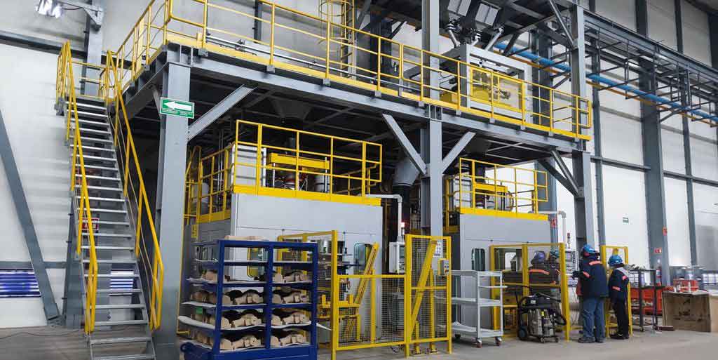
The subject steel casting exemplifies the trend toward larger components, with outline dimensions of 4425 mm × 3945 mm × 1200 mm and a finished weight of approximately 54 metric tons (rough casting weight ~60 t). This scale imposes rigorous demands on manufacturing equipment. The machine tool must provide ample travel in all axes to accommodate the part, and its rotary table must have exceptional load-bearing capacity. Selecting inadequate machinery would compromise precision, tool accessibility, and operational safety. The specifications for a suitable machining center can be summarized as follows:
- X and Y-axis travel: ≥ 5000 mm.
- Z-axis travel: > (Anchorage face thickness + 200 mm).
- Rotary table capacity: > 60 t, with table dimensions ≥ 5000 mm × 5000 mm.
2. Challenge of Complex Geometry and Dimensional Accuracy
The geometry of the steel casting is an irregular hexahedron. The primary machining datum is the “anchor face.” While two side plates are perpendicular to this face, the top and bottom plates are oriented at compound angles. The bottom plate has a longitudinal slope (α₁), and the top plate possesses both a longitudinal slope (α₂) and a transverse slope (α₃).
$$ \text{Bottom Plate Angle relative to Datum: } \alpha_1 $$
$$ \text{Top Plate Longitudinal Angle: } \alpha_2 $$
$$ \text{Top Plate Transverse Angle: } \alpha_3 $$
These compound angles make conventional machining, which requires the machined surface to be perpendicular to the spindle axis, highly inefficient. It would necessitate multiple setups, complex fixturing, and precise realignment for each surface, increasing both the risk of cumulative error and labor intensity.
3. Challenge of Spatially Oriented Anchor Holes
This is the most intricate challenge. A single steel casting can contain dozens of anchor holes (e.g., 61 in our case). Each hole’s axis is defined by a unique compound angle relative to the anchor face datum. This spatial orientation is typically described by two angles: the projection of the hole axis onto the anchor face relative to a principal axis (α₄), and the acute angle between the hole axis and its projection on the anchor face (α₅).
$$ \text{Projection Angle on Datum Plane: } \alpha_4 $$
$$ \text{Inclination Angle from Datum Plane: } \alpha_5 $$
Conventional methods to machine such spatial holes are profoundly inefficient:
- Method A (Repositioning Workpiece): For each hole, the massive casting is repositioned so the specific hole axis is vertical to the spindle. This is physically demanding and time-prohibitive.
- Method B (Using Universal Angle Heads): A universal head is adjusted to a unique compound angle for each hole. While precise, the repeated manual adjustment for dozens of holes is extremely laborious and slow.
Both conventional methods result in unacceptable production times and high potential for error, necessitating a novel, integrated machining approach.
Integrated Machining Strategy and Solutions
To address these challenges holistically, a strategy was developed centered on a high-capacity CNC floor-type boring and milling machine with a precision rotary table. For our application, a TK6926 machine was selected with the following key capabilities: X-axis travel 18m, Y-axis 6m, Z-axis 1.6m, a 140t capacity 5000mm×5000mm CNC rotary table (B-axis), and a high-precision control system enabling multi-axis interpolation.
1. Efficient Machining of Complex External Geometry
The strategy leverages the CNC rotary table to minimize setups. The entire external machining is completed in only two primary setups, drastically reducing alignment time and cumulative error compared to the six or more setups required by traditional methods.
Setup 1: Machining the Datum (Anchor Face) and Vertical Sides.
The casting is placed on the rotary table with the bottom plate supported on adjustable blocks to establish the longitudinal angle α₁. This orientation automatically positions the anchor face perpendicular to the machine spindle (Z-axis). After machining the anchor face, the side plates, which are perpendicular to the datum, are machined by simply commanding the rotary table (B-axis) to rotate 90° and 270° sequentially.
Setup 2: Machining the Thickness, Bottom, and Compound-Angle Top Plate.
The casting is repositioned with one side plate down on the table, making the “grid surface” (defining thickness) perpendicular to the spindle. After machining this surface, the bottom plate is machined by rotating the table by (90° + α₁).
Machining the top plate, with its compound angles α₂ and α₃, requires a multi-axis contouring move. The table is first rotated to the orientation for the longitudinal angle (270° + α₂). To achieve the transverse slope α₃, the machine executes a linear interpolation simultaneously in the Y and Z axes, creating a ruled surface. The surface finish and flatness are controlled by calculating the optimal stepover distance to minimize cusp height. The maximum scallop height (h) for a given stepover (s) and effective tool radius (R) for a slope can be approximated by:
$$ h \approx R – \sqrt{R^2 – \left(\frac{s}{2}\right)^2} \cdot \cos(\alpha_3) $$
For a required surface roughness, the maximum allowable stepover (s_max) can be derived:
$$ s_{max} \approx 2 \cdot \sqrt{ 2R \cdot \frac{h_{allowed}}{\cos(\alpha_3)} – \left( \frac{h_{allowed}}{\cos(\alpha_3)} \right)^2 } $$
A comparison of setup efficiency clearly demonstrates the advantage:
| Machining Method | Number of Setups | Estimated Time per Setup (hours) | Total Setup Time (hours) |
|---|---|---|---|
| Conventional (without full CNC table) | 6 | 4 | 24 |
| Proposed Integrated Method | 2 | 4 | 8 |
2. High-Efficiency Machining of Spatial Anchor Holes
The innovative solution for the anchor holes capitalizes on multi-axis (X, Y, Z) linear interpolation, or “slant drilling/boring,” while the workpiece remains in the same Setup 1 orientation (anchor face vertical to spindle). Instead of aligning the tool axis perpendicular to each hole, the tool path is calculated to follow the projected direction of the hole’s axis. The complex 3D hole direction is decomposed into its directional components.
For a given hole with angles α₄ and α₅ relative to the anchor face (XY-datum plane with Z vertical), the unit direction vector v of the hole axis is:
$$ \mathbf{v} = \begin{pmatrix} \sin(\alpha_5) \cdot \cos(\alpha_4) \\ \sin(\alpha_5) \cdot \sin(\alpha_4) \\ \cos(\alpha_5) \end{pmatrix} $$
When the anchor face is vertical (parallel to machine YZ plane), a coordinate transformation is applied. The machining path for a hole of length L involves moving the tool simultaneously in X, Y, and Z from the entry point along the vector components of v in the machine coordinate system. While this produces a theoretically elliptical tool engagement with a round-nose tool, the deviation from a perfect circle is within the strict tolerances required for cable anchorage. The primary advantage is that all holes are machined in a single setup without any physical adjustment of the workpiece or attachment angle head.
The efficiency gain is transformative:
| Machining Method for Holes | Number of Adjustments | Estimated Time per Adjustment (hours) | Total Adjustment Time (hours) |
|---|---|---|---|
| Conventional A (Reposition Part) | 60 (once per hole) | 5 | 300 |
| Conventional B (Adjust Angle Head) | 60 (once per hole) | 2 | 120 |
| Proposed Slant Boring Method | 0 (Same as Setup 1) | 0 | 0* |
* Only the CNC programming time is added; no physical setup time.
Process Implementation and Quality Assurance
The successful implementation of this strategy for large steel castings relies on meticulous process planning. Key steps include:
- Tool Path Optimization: CAM software is used to generate efficient tool paths for both face milling and the multi-axis hole boring cycles, ensuring optimal feed rates and minimizing non-cutting time.
- Tooling Selection: Robust boring bars with carbide inserts and specialized face mills are selected to handle the interrupted cuts typical of cast surfaces and the long reaches required for deep holes.
- In-Process Verification: Probing cycles are integrated into the CNC program to verify critical datum features after setup and to check the position of key anchor holes, allowing for mid-process compensation if needed.
- Control of Thermal Effects: For large steel castings, managing heat generated during machining is crucial to prevent thermal distortion. This is achieved through consistent use of coolant, periodic pauses for thermal equilibrium on critical finishing passes, and sequencing operations to balance material removal.
The mathematical control of surface finish for compound angles, as shown earlier, is integral to the process documentation. The allowable stepover (s_max) is calculated for the specific top plate angle α₃ and programmed accordingly, ensuring the final surface meets the required roughness (e.g., Ra 3.2 μm) without unnecessary slow passes.
Conclusion
The machining of large, complex steel castings for self-anchored suspension bridges demands an integrated approach that transcends conventional piecemeal methods. By analyzing the inherent challenges—size, compound geometry, and spatial holes—and leveraging the full capabilities of modern CNC machinery with precision rotary tables, a highly efficient processing technology has been established. This methodology, centered on strategic two-setup machining and multi-axis slant boring, delivers exceptional benefits:
- Dramatic Reduction in Non-Productive Time: Setup times are reduced by over 65% for external surfaces, and spatial hole machining time is reduced by orders of magnitude.
- Enhanced Accuracy and Repeatability: Minimizing setups reduces cumulative alignment errors. CNC interpolation ensures precise and repeatable hole angles.
- Significant Lowering of Labor Intensity: Eliminating the manual repositioning of 60-ton castings or the adjustment of angle heads for dozens of holes transforms a grueling task into a managed, automated process.
The techniques detailed herein provide a robust and efficient framework for machining critical steel casting components. They offer valuable insights not only for bridge engineering but also for other industries facing similar challenges in machining large, heavy workpieces with compound surfaces and spatially oriented features. The continued advancement of such integrated machining strategies is essential for the economic and reliable construction of next-generation infrastructure.