
The production of large, thin-walled aluminum alloy castings for demanding applications like high-voltage electrical equipment and heavy-duty power units presents significant technical challenges. These components, often serving as pressure vessels or structural parts with stringent airtightness requirements, cannot tolerate defects such as shrinkage porosity, gas holes, or inadequate mechanical properties. For over a decade, my research and development efforts have focused on perfecting a robust and economical low-pressure sand casting technology tailored for these complex parts. This integrated approach encompasses metallurgical quality enhancement, innovative mold design, specialized equipment development, and advanced core-making techniques, all converging to achieve high-integrity castings that consistently meet international standards.
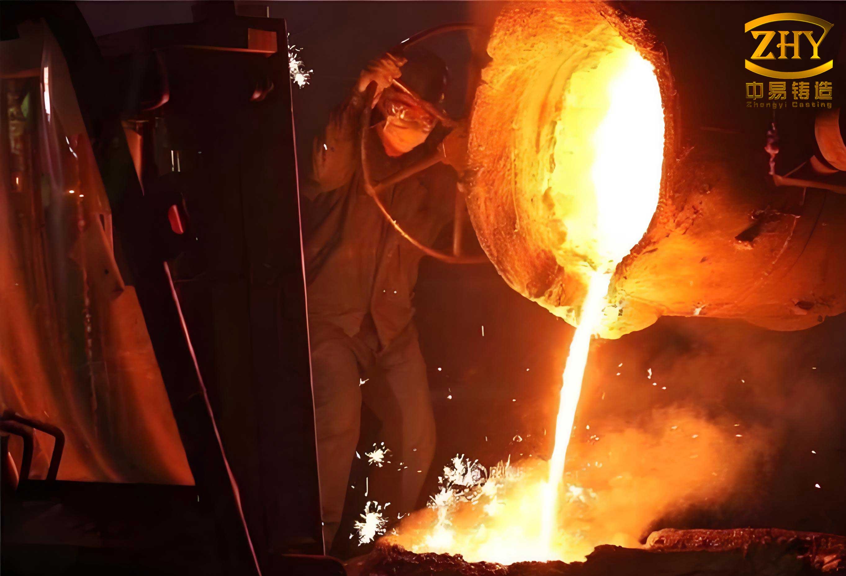
1. Metallurgical Foundations: Alloy Design and Melt Quality
The cornerstone of reliable casting is superior melt quality. For components requiring a balance of castability, strength, elongation, and—critically for electrical parts—conductivity, the Al-Si-Mg system (akin to A356/ZL101A) is the baseline. However, standard composition ranges are too broad for optimal performance.
1.1 Optimized Composition for Performance Trade-offs
Key alloying elements have conflicting effects. Silicon (Si) improves fluidity, essential for filling thin sections in sand casting, but detrimentally impacts electrical conductivity. The relationship can be approximated for dilute alloys by Nordheim’s rule, but in practice, a narrow, optimized window is sought. Magnesium (Mg), forming the strengthening Mg₂Si phase, also reduces conductivity. Our work determined the optimal compromise lies in a tighter Si range than standard and a Mg content between 0.3-0.5 wt.%.
$$ \text{Conductivity} \propto \frac{1}{C_{Si} + k \cdot C_{Mg}} $$
Where \( C_{Si} \) and \( C_{Mg} \) are weight percentages and \( k \) is a coefficient reflecting Mg’s stronger detrimental effect per unit weight compared to Si.
The role of impurities is often understated. While iron (Fe) is commonly controlled, phosphorus (P) and calcium (Ca) are equally harmful. P, primarily originating from metallurgical-grade silicon, promotes the formation of AlP nuclei, leading to coarse, plate-like eutectic Si that degrades mechanical properties and conductivity. Using high-purity silicon sources is non-negotiable. Ca increases melt susceptibility to hydrogen pickup and causes surface defects.
| Element | Primary Role/Effect | Optimal/Target Range (wt.%) | Detrimental Effect if Excessive | Control Method |
|---|---|---|---|---|
| Si | Improves fluidity, castability | 6.8 – 7.2 | Reduces conductivity & elongation | Use of high-purity Si source |
| Mg | Forms Mg₂Si for strength | 0.30 – 0.50 | Reduces conductivity & ductility | Precise addition via master alloy |
| Ti | Grain refiner (forms Al₃Ti) | 0.10 – 0.15 | Can form coarse intermetallics | Secondary addition via salt-based refiners |
| Fe | Impurity (forms β-Al₅FeSi) | < 0.15 | Reduces ductility, promotes cracking | Use of high-purity Al feedstock |
| P | Impurity (forms AlP) | < 0.0015 | Coarsens Si structure, reduces properties | Use of high-purity Si (>99.9%) |
| Ca | Impurity | < 0.001 | Increases hydrogen pickup, causes surface defects | Specification for low-Ca primary aluminum |
| RE (La, Ce) | Modifies eutectic Si, getters H | 0.05 – 0.15 | Can form sludge if over-added | Late addition as Al-RE master alloy |
| B, Zr | Supplementary grain refinement | 0.005 – 0.02 | — | Included in composite grain refiner salts |
1.2 Advanced Melt Treatment Practices
Superior melt treatment involves a multi-stage approach to grain refinement, hydrogen removal, and inclusion elimination.
Secondary Grain Refinement: Conventional grain refinement via Al-Ti-B master alloys added during primary ingot production loses potency during remelting due to fading (agglomeration and settling of TiB₂ and Al₃Ti particles). A “secondary addition” technique was developed, introducing a salt-based refiner containing Ti, B, and Zr just before casting. This generates a fresh, highly potent population of nucleants (Al₃Ti, TiB₂, Al₃Zr), dramatically refining the as-cast grain structure according to the free growth model.
Integrated Melt Purification: Hydrogen porosity and oxide inclusions are the primary defects affecting airtightness in sand casting. A multi-functional flux was developed that combines degassing, modification, and fluxing actions. When added at ~720°C, it releases inert gases that float hydrogen to the surface via:
$$ J_H \propto (C_{H, melt} – C_{H, bubble}) \cdot \sqrt{D_H \cdot \dot{N}_b \cdot r_b} $$
Where \( J_H \) is hydrogen removal flux, \( C_H \) is concentration, \( D_H \) is diffusivity, \( \dot{N}_b \) is bubble generation rate, and \( r_b \) is bubble radius. Simultaneously, rare earth (RE) elements in the flux modify the eutectic Si morphology and react with residual hydrogen to form stable hydrides (e.g., CeH₃), preventing its precipitation as gas pores during solidification.
For high-volume production, a rotary degassing system with pulsed inert gas injection was implemented. Pulsation creates a finer bubble distribution, increasing the total bubble surface area and residence time, thereby maximizing the efficiency of hydrogen and inclusion removal as described by the mass transfer coefficient.
| Treatment | Mechanism | Key Parameters | Advantages | Limitations |
|---|---|---|---|---|
| Multi-Functional Flux | Chemical reaction, gas flotation | Temperature: 720-740°C, Addition: 0.5-1.0% | Combined degassing, modification, cleaning; simple, low cost | Efficiency depends on mixing; some dross generation |
| Rotary Degassing (Pulsed) | Physical mass transfer | Rotation: 300-500 RPM, Gas Flow: Pulsed, Time: 8-15 min | High and consistent removal efficiency for [H] & inclusions; suitable for large volumes | Higher equipment cost; requires skilled operation |
| Secondary Ti-B-Zr Salt Addition | Heterogeneous nucleation | Addition: 0.1-0.2%, Temp: <750°C, Holding: <30 min | Superior, fade-resistant grain refinement; fine equiaxed structure | Must be added late in process; limited holding time |
2. Precision Mold Engineering for Sand Casting
Large castings with thin walls and heavy flanges demand exceptional dimensional accuracy and controlled solidification. Traditional sand casting practices for cores and chills were insufficient.
2.1 Chill Design and Surface Engineering
Heavy flanges and sealing faces are prone to shrinkage porosity. Using chills is standard, but their improper application leads to defects. We specified ductile iron for its consistent thermal properties. More critically, chills undergo machining to ensure flatness and incorporate vent channels (≈20 mm apart) to allow air escape. The most vital step is surface treatment: after shot blasting, chills are salt-bath nitrided. This creates a hard, oxidation-resistant Fe₂₋₃N layer that prevents rust (Fe₃O₄). Rust is hygroscopic; upon contact with molten Al, it decomposes, releasing hydrogen which leads to pinholing in the very sealing surface the chill is meant to protect. The effectiveness of a chill is governed by the interfacial heat transfer coefficient (IHTC) and its thermal diffusivity \( \alpha \):
$$ \alpha = \frac{k}{\rho c_p} $$
Where \( k \) is thermal conductivity, \( \rho \) is density, and \( c_p \) is specific heat. A clean, nitride-treated surface maintains a higher, more consistent IHTC than a rusted or painted one.
2.2 Mold Core Positioning System
A revolutionary improvement was made to core positioning. Traditional sand cores use sand core prints, which require draft and clearance (1-1.5 mm) to avoid damage during mold assembly, leading to core shift and wall thickness variation of 2-3 mm. Our system integrates the precision-machined chills surrounding a flange with a matching metal core print. The core itself is built around a steel tube (replacing a bulky, traditional iron core barrel) using a special fixture, creating a hollow, easy-to-bake-and-remove structure. Its print is a machined metal plate. This assembly fits into the “socket” formed by the chills with a metal-to-metal clearance of only ~0.5 mm. This hybrid approach brings the locational accuracy of permanent mold casting to sand casting, reducing wall thickness deviation to less than 1 mm and ensuring perfect alignment of critical features.
3. Low-Pressure Sand Casting Process and Equipment Innovation
For large, thin-walled vessels requiring pressure tightness, gravity pouring in sand casting is problematic: turbulent flow causes oxide entrainment, and inadequate feeding leads to shrinkage. Low-pressure casting offers a superior solution by providing counter-gravity filling and sustained pressure during solidification.
3.1 Process Advantages and Parameters
In low-pressure sand casting, the mold is placed atop a sealed furnace holding the molten alloy. Pressurized gas (typically dry air or nitrogen) forces melt up a refractory tube (stalk) into the mold cavity. The key benefits are:
1. Non-Turbulent Filling: Melt rises smoothly from the bottom, minimizing oxide entrainment and air aspiration. The velocity \( v \) should be below the critical threshold for surface turbulence.
2. Controlled Fill Rate: The pressure curve \( P(t) \) is programmable. An initial rapid rise overcomes surface tension, followed by a steady pressure increase to maintain a constant metallostatic head for laminar filling, and finally an intensification pressure for feeding.
3. Directional Solidification Aid: The applied pressure \( P_{app} \) directly improves feeding by increasing the effective feeding distance and suppressing the formation of microporosity. The relationship can be simplified as:
$$ d_{feeding} \propto \frac{\Delta T}{G} + \frac{P_{app}}{\rho g} $$
Where \( \Delta T \) is freezing range, \( G \) is thermal gradient, \( \rho \) is density, and \( g \) is gravity.
4. Improved Yield: The pressurization system replaces traditional risers, giving yields often exceeding 85%.
| Phase | Purpose | Pressure Control | Key Physical Principle | Effect on Casting |
|---|---|---|---|---|
| Filling | To fill cavity completely without turbulence | Linear increase to achieve desired metal velocity (e.g., 5-15 mm/s) | Bernoulli’s Principle: \( P + \frac{1}{2}\rho v^2 + \rho gh = constant \) | Minimizes oxide entrainment and gas defects |
| Intensification | To feed shrinkage during solidification | Step increase or ramp to final pressure (0.5-0.8 bar gauge) | Darcy’s Law for flow through mushy zone: \( v = \frac{K}{\mu} \nabla P \) | Reduces shrinkage porosity, increases density |
| Hold | To allow complete solidification under pressure | Maintain intensification pressure | Heat transfer: \( \frac{\partial T}{\partial t} = \alpha \nabla^2 T \) | Ensures soundness in thick sections |
3.2 Crucible-Sealed Equipment Design
Commercial low-pressure casting machines use “furnace-sealed” designs where the mold load is borne by the furnace shell and lining. This is unsuitable for the massive molds used in our sand casting process (e.g., molds weighing over 13 tons). Our patented innovation is a “crucible-sealed” system. Here, the pressure vessel is the crucible itself. The mold’s weight is supported by a robust steel frame independent of the furnace. This offers several advantages:
1. The furnace lining experiences no mechanical stress, drastically extending its life.
2. The crucible, made from a specially formulated high-temperature creep-resistant alloy, is designed to withstand the combined thermal and pressure cycling. Its life exceeds 150 cycles.
3. Pressure control is more stable and responsive as the gas volume above the melt is smaller and more defined compared to a furnace-sealed system.
This simple, robust, and highly adaptable design is a key enabler for large-scale sand casting via low-pressure, requiring significantly lower investment than conventional machines of similar capacity.
4. Advanced Core Making for Complex Internal Features
Some components, like connector tubes, have small, enclosed internal cavities with high surface finish requirements, where internal machining or blasting is impossible. Traditional core-making resulted in dimensional inaccuracies, poor surface finish, and poor collapsibility, leading to high scrap rates.
The solution was a “negative pattern” or “female-male” core-making technique. First, a precision-machined metal positive model of the desired internal cavity is created. A zero-shrinkage silicone rubber is molded around this model to create a perfect negative replica core box. A modified, highly collapsible sodium silicate sand (with enhanced breakdown properties) is then packed into this rubber mold. The resulting sand core replicates the dimensions and surface finish of the original metal model with high fidelity. When used in the low-pressure sand casting process, it produces an internal surface that requires no further finishing. The modified silicate binder ensures the core disintegrates easily after casting under mechanical vibration, leaving a clean cavity.
5. Integrated Process Design and Simulation
The development of a robust process for a new large casting is underpinned by Computer-Aided Design (CAD) and solidification simulation. A 3D model of the part is created, and initial feeding and gating systems are designed virtually. Simulation software solves the governing equations of fluid flow and heat transfer during filling and solidification:
Continuity: $$ \nabla \cdot \vec{v} = 0 $$
Momentum (Navier-Stokes with Darcy term for mushy zone): $$ \frac{\partial \vec{v}}{\partial t} + (\vec{v} \cdot \nabla) \vec{v} = -\frac{1}{\rho} \nabla P + \nu \nabla^2 \vec{v} + \vec{g} – \frac{\mu}{K} \vec{v} $$
Energy: $$ \frac{\partial T}{\partial t} + \vec{v} \cdot \nabla T = \nabla \cdot (\alpha \nabla T) + \frac{L}{c_p} \frac{\partial f_s}{\partial t} $$
Where \( \vec{v} \) is velocity, \( P \) is pressure, \( \nu \) is kinematic viscosity, \( \mu \) is dynamic viscosity, \( K \) is permeability, \( L \) is latent heat, and \( f_s \) is solid fraction. By predicting shrinkage porosity and potential hot spots, the process (placement of chills, vents, pressure curve) can be optimized digitally before any tooling is made, saving substantial time and cost.
6. Conclusion: A Validated Manufacturing Solution
The integrated low-pressure sand casting technology described herein represents a comprehensive solution for manufacturing high-integrity, large aluminum alloy castings. It synergistically combines:
- Metallurgical Excellence: Through optimized Al-Si-Mg chemistry, stringent impurity control, and advanced melt treatment to achieve a fine-grained, clean melt with balanced properties.
- Precision Mold Technology: Utilizing engineered chills and a metal-sand hybrid core positioning system to achieve dimensional accuracy rivaling more expensive processes.
- Robust and Adaptable Process: Leveraging the inherent benefits of low-pressure casting—laminar filling and pressurized solidification—with a uniquely simple and strong crucible-sealed equipment design suitable for very large sand casting molds.
- Specialized Core Making: Enabling the production of complex internal geometries with excellent surface finish and dimensional fidelity.
This technology has been proven over more than a decade of production across multiple foundries, producing thousands of components such as high-voltage switchgear tanks, transformer housings, and engine blocks. The castings exhibit dense microstructure, excellent pressure tightness (meeting the stringent ≤1% annual SF₆ leakage rate), and superior mechanical and electrical properties. Their consistent quality has enabled supply to leading global engineering corporations, demonstrating that sophisticated, high-performance aluminum castings can be reliably and cost-effectively manufactured using an advanced sand casting approach.