
The integration of computer simulation into the casting process has fundamentally reshaped the landscape of manufacturing and materials science. It is now widely recognized as an essential frontier for technological advancement and the indispensable path for modernizing traditional foundry practices. The inherent complexity of solidification, where molten metal transforms into a solid component, is fraught with the potential for forming internal flaws. These flaws, primarily shrinkage cavities, shrinkage porosity, and hot tears, pose significant risks to the structural integrity, mechanical performance, and service life of the final product. Consequently, the ability to predict and mitigate these casting defects is paramount. Numerical simulation provides a powerful virtual prototyping tool, enabling a detailed analysis of the thermal and mechanical events during pouring and solidification. By creating a digital twin of the casting process, we can visualize potential failure sites, optimize design parameters, and refine production techniques before any metal is poured. This proactive approach is a cornerstone for ensuring casting quality, reducing scrap rates, and accelerating product development cycles. In this comprehensive exploration, I will detail the methodologies for simulating the transient temperature and stress-strain fields during solidification, focusing on their application for predicting the locations of shrinkage-related defects and assessing the risk of hot cracking.
The physical foundation for any casting simulation lies in accurately modeling heat transfer. The core of this modeling is the transient heat conduction equation. In a three-dimensional domain, the temperature field variable \( T(x, y, z, t) \) must satisfy the following governing differential equation in Cartesian coordinates:
$$c\rho \frac{\partial T}{\partial t} – k\left(\frac{\partial^2 T}{\partial x^2} + \frac{\partial^2 T}{\partial y^2} + \frac{\partial^2 T}{\partial z^2}\right) = g \quad \text{in } \Omega$$
Here, \( T \) represents temperature (°C), \( t \) is time (s), \( c \) is the specific heat capacity (J/(kg·°C)), \( \rho \) is the density (kg/m³), \( k \) is the thermal conductivity coefficient (W/(m·°C)), and \( g \) is the internal heat source strength (W/m³). This equation is a statement of energy balance: the rate of heat accumulation within a differential volume (left term) equals the net heat conduction into the volume plus the heat generated internally. The solution to a transient thermal problem involves finding the temperature field function \( T \), which depends on both spatial coordinates and time, that satisfies this equation subject to specific initial and boundary conditions.
The boundary conditions are critical for defining the interaction between the casting system (the domain \( \Omega \)) and its surroundings. Three classic types are employed:
- Dirichlet (First-type) Condition: Specifies the temperature on the boundary surface \( \Gamma \).
$$T|_{\Gamma} = f_1(x, y, z, t)$$ - Neumann (Second-type) Condition: Specifies the heat flux across the boundary.
$$k \frac{\partial T}{\partial n}|_{\Gamma} = q$$ - Robin (Third-type) Condition: Defines convection (or combined convection-radiation) heat transfer with the environment.
$$k \frac{\partial T}{\partial n}|_{\Gamma} = h (T – T_{\infty})$$
In these equations, \( n \) is the outward normal to the boundary, \( q \) is the imposed heat flux (W/m²), \( h \) is the heat transfer coefficient (W/(m²·°C)), and \( T_{\infty} \) is the ambient temperature. In casting simulations, the mold-air interfaces are typically modeled using the third-type condition, with \( h \) values calibrated for different mold surfaces (top, bottom, sides). The initial condition is defined as \( T = T_0 \) throughout the domain at time \( t = 0 \), where \( T_0 \) is the initial temperature (e.g., pouring temperature for the metal, preheat temperature for the mold).
Numerical Analysis of the Temperature Field
The simulation of temperature fields in casting is a quintessential nonlinear transient heat transfer problem. Material properties such as thermal conductivity (\( k \)), specific heat (\( c \)), and density (\( \rho \)) are strongly dependent on temperature, especially across the liquidus and solidus range. Furthermore, the release of latent heat during the liquid-to-solid phase transformation represents a significant internal energy source that drastically influences the cooling curve. This latent heat (\( L \)) is often handled efficiently by defining the enthalpy (\( H \)) of the material as a function of temperature:
$$H(T) = \int_{T_{ref}}^{T} \rho(\tau) c(\tau) \, d\tau + f_s L$$
where \( f_s \) is the solid fraction. Modern simulation software allows for the direct input of enthalpy data, simplifying the incorporation of phase change effects. The finite element method (FEM) is exceptionally well-suited for solving this complex problem on intricate casting geometries. Using 3D solid thermal elements (e.g., SOLID70 in ANSYS), the casting-mold system is discretized into a mesh. The nonlinear transient analysis proceeds by solving the discretized form of the heat conduction equation at each time step, accounting for the temperature-dependent properties and the enthalpy jump.
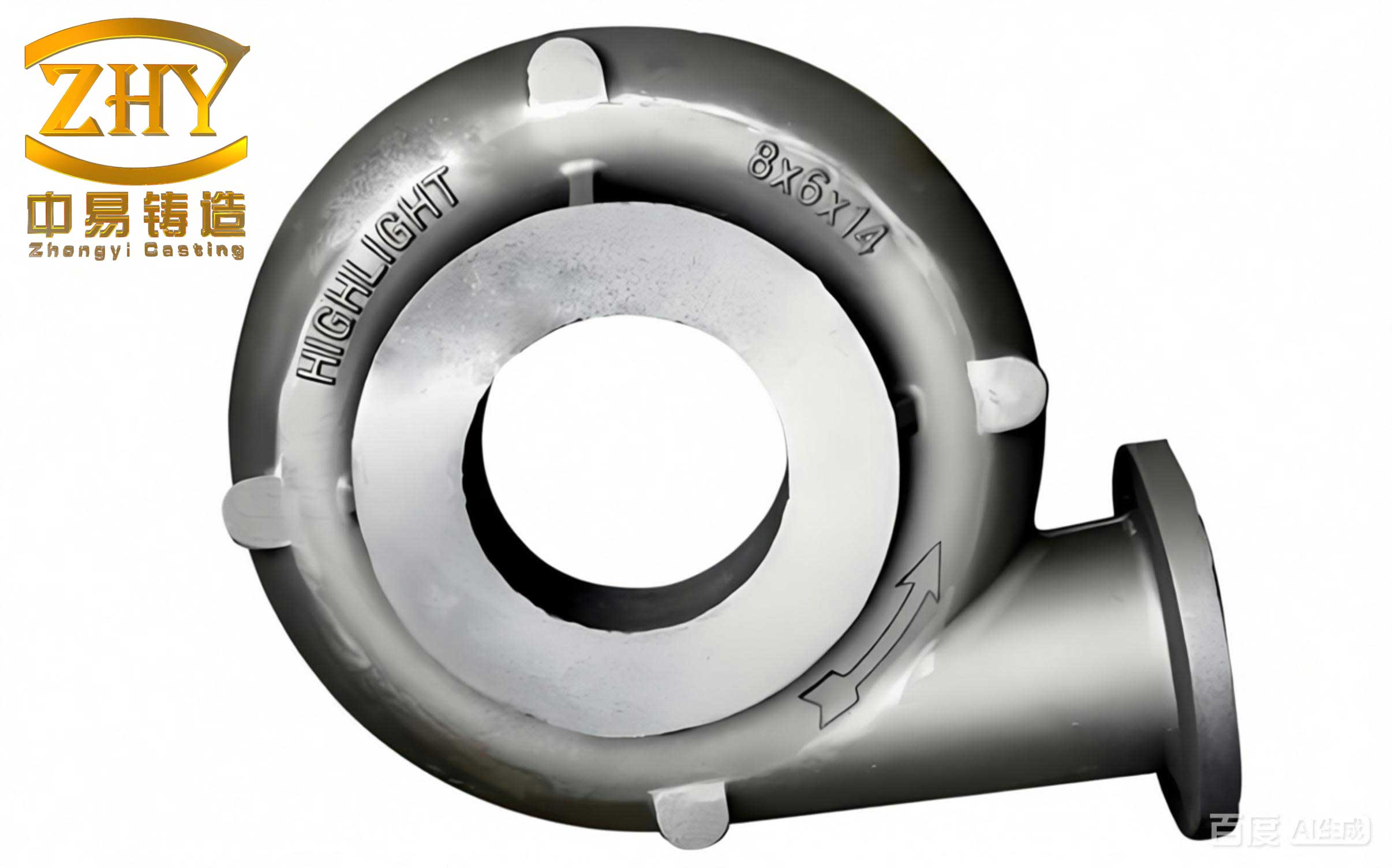
The primary output is the evolution of the temperature field \( T(x,y,z,t) \). From this, other critical fields are derived, most importantly the temperature gradient \( \vec{G} = \nabla T \). The magnitude of the gradient, \( G = |\vec{G}| \), and its direction are fundamental to understanding solidification morphology and defect formation. Regions with low gradients and slow cooling rates are particularly susceptible to certain casting defects.
Predicting Shrinkage Cavities and Porosity
Shrinkage cavities and micro-porosity are among the most common and detrimental casting defects. They result from the volumetric contraction of the metal as it cools and solidifies, compounded by insufficient feeding from risers. Numerical simulation predicts these defects by employing solidification feeding criteria. The most widely used criteria are based on the local thermal parameters: temperature gradient (\( G \)) and solidification rate (\( R \)), where \( R \) is the velocity of the isotherm moving through the material.
One prominent criterion is the Niyama criterion, originally developed for steel castings but often adapted. It states that shrinkage porosity is likely when the following condition is met:
$$\frac{G}{\sqrt{R}} < C_{\text{Niyama}}$$
Here, \( C_{\text{Niyama}} \) is a threshold constant specific to the alloy. A lower value of \( G/\sqrt{R} \) indicates a region that is thermally isolated, cools slowly, and is difficult to feed, leading to pore formation.
Another well-known approach is the Shinagawa (New山) criterion, which uses a similar ratio but with a different exponent for the solidification time (\( t_f \)):
$$\frac{G}{R^{1/2}} = \frac{G}{[(T_2 – T_1) / (t_2 – t_1)]^{1/2}}$$
Where \( (T_2 – T_1) \) is the temperature drop at a node over the time interval \( (t_2 – t_1) \). Empirical and theoretical work suggests that a critical value exists, often around 0.7 °C¹/²·s¹/²·m⁻¹ for many alloys. Nodes or elements where \( G/R^{1/2} \) falls below this critical value are flagged as potential sites for shrinkage porosity or cavities.
The process can be demonstrated with simulated data. The following table illustrates the calculation for selected nodes from a gray iron casting simulation at different time steps (44s and 3500s):
| Node ID | T@44s (°C) | G (℃/m) | T@3500s (°C) | ΔT (℃) | Δt (s) | R¹/² (℃¹/²/s¹/²) | G/R¹/² | Defect Risk (C<0.7) |
|---|---|---|---|---|---|---|---|---|
| 1682 | 152.85 | 6.91 | 144.71 | 8.14 | 500 | 0.13 | 0.53 | High |
| 1683 | 198.24 | 8.00 | 184.10 | 14.14 | 500 | 0.17 | 0.47 | High |
| 1684 | 235.71 | 9.61 | 214.89 | 20.82 | 500 | 0.20 | 0.48 | High |
| 2311 | 287.39 | 19.33 | 265.32 | 22.07 | 250 | 0.30 | 0.64 | High |
| 486 | 196.83 | 12.17 | 195.13 | 1.70 | 250 | 0.08 | 1.52 | Low |
| 1663 | 328.42 | 98.77 | 320.60 | 7.82 | 250 | 0.18 | 5.49 | Low |
As shown, nodes 1682, 1683, 1684, and 2311 have \( G/R^{1/2} \) values significantly below the 0.7 threshold, identifying them as high-risk locations for shrinkage defects. These locations typically correspond to thermal centers, hot spots, or isolated sections of the casting that solidify last. Validating such predictions against actual castings confirms a strong correlation, making this a reliable method for optimizing riser placement and cooling design to eliminate these casting defects.
Simulation of Thermo-Mechanical Stresses and Hot Tearing
While shrinkage porosity is primarily a thermal phenomenon, hot tearing is a mechanical failure that occurs in the late stages of solidification when the material is in a semi-solid, mushy state. It arises when thermal contraction (shrinkage) is mechanically restrained—by the rigid mold, a rigid core, or even other parts of the casting itself—generating tensile stresses and strains that exceed the very low ductility and strength of the coherent solid network.
Predicting hot tears requires a coupled thermo-mechanical simulation. The process is sequential: the calculated transient temperature field serves as the thermal load input for the stress analysis. The fundamental equation governing the mechanical response is the equilibrium equation:
$$\nabla \cdot \boldsymbol{\sigma} + \mathbf{b} = 0 \quad \text{in } \Omega$$
where \( \boldsymbol{\sigma} \) is the Cauchy stress tensor and \( \mathbf{b} \) is the body force vector (often negligible in casting). The key link between the thermal and mechanical analyses is the thermal strain. The total strain \( \boldsymbol{\varepsilon}_{total} \) is decomposed into elastic (\( \boldsymbol{\varepsilon}_{el} \)), plastic (\( \boldsymbol{\varepsilon}_{pl} \)), and thermal (\( \boldsymbol{\varepsilon}_{th} \)) components:
$$\boldsymbol{\varepsilon}_{total} = \boldsymbol{\varepsilon}_{el} + \boldsymbol{\varepsilon}_{pl} + \boldsymbol{\varepsilon}_{th}$$
The thermal strain is directly calculated from the temperature history:
$$\boldsymbol{\varepsilon}_{th} = \alpha (T – T_{ref}) \mathbf{I}$$
where \( \alpha \) is the coefficient of thermal expansion (which is also temperature-dependent) and \( \mathbf{I} \) is the identity tensor. The material’s constitutive law (stress-strain relationship) in the solid state is highly nonlinear, requiring sophisticated models that account for elastic-plastic-creep behavior, especially at high temperatures near the solidus.
The output of the stress analysis is the evolution of the stress and strain tensors throughout the casting. To assess the risk of failure, a scalar equivalent stress is often used. The von Mises equivalent stress (\( \sigma_{vm} \)), based on the distortion energy theory (4th strength theory), is a common measure:
$$\sigma_{vm} = \sqrt{\frac{1}{2}\left[(\sigma_1 – \sigma_2)^2 + (\sigma_2 – \sigma_3)^2 + (\sigma_1 – \sigma_3)^2 \right]}$$
where \( \sigma_1, \sigma_2, \sigma_3 \) are the principal stresses. However, the critical threshold for failure is not a constant like yield strength; it is the temperature-dependent tensile strength of the material in the mushy and solid states, \( \sigma_b(T) \). This property is extremely low just below the solidus and increases as temperature decreases.
A practical hot tearing criterion, therefore, involves comparing the simulated stress to this evolving strength. One proposed criterion defines a vulnerability index \( K_w \):
$$K_w = \frac{\sigma_{vm}}{\sigma_b(T)}$$
Hot tearing is predicted to occur at locations and times where \( K_w \geq 1 \). Implementing this requires accurate data for \( \sigma_b(T) \) from the solidus down to room temperature, which can be obtained from high-temperature tensile tests or literature. The following table illustrates the concept using data from a stress simulation of a standard test casting:
| Time (s) | Node Temp. (°C) | Von Mises Stress, σ (MPa) | Tensile Strength, σ_b(T) (MPa) | Vulnerability Index, K_w |
|---|---|---|---|---|
| 92 | 1106.9 | 0.117 | 24.6 | 0.005 |
| 117 | 1075.7 | 0.211 | 25.0 | 0.008 |
| 242 | 920.0 | 0.284 | 34.0 | 0.008 |
| 442 | 720.0 | 0.548 | 46.0 | 0.012 |
| 542 | 635.0 | 0.610 | 51.0 | 0.012 |
| 642 | 580.0 | 0.726 | 57.5 | 0.013 |
| 742 | 538.0 | 0.900 | 60.6 | 0.015 |
In this example, \( K_w \) remains far below 1, indicating a low risk of hot tearing for this particular casting and material under the simulated conditions. The analysis reveals that while stresses increase as the casting cools (due to greater constraint and stiffness), the tensile strength increases at a faster rate. The peak risk period is often in the temperature range just below the solidus, where strength is minimal but contraction stresses begin to build. Simulation allows engineers to identify geometric features that act as stress concentrators (sharp corners, sudden section changes) and periods during cooling where restraint is highest, guiding design modifications like fillet radii or the use of compliant mold coatings to reduce the incidence of these critical casting defects.
Material Properties and Process Parameters
The accuracy of any numerical simulation is directly tied to the quality of the input data. For casting simulation, this means comprehensive thermophysical and mechanical properties for both the alloy and the mold materials across the relevant temperature range. Key properties include:
| Property | Symbol | Importance in Simulation | Typical Variation |
|---|---|---|---|
| Thermal Conductivity | k(T) | Governs rate of heat extraction. Can differ significantly between liquid and solid states. | Nonlinear, often decreases in liquid for metals. |
| Specific Heat | c_p(T) | Determines energy required for temperature change. Latent heat is a key component. | Peak at phase change due to latent heat. |
| Density | ρ(T) | Affects thermal mass and buoyancy-driven flow (not in pure conduction models). Shrinkage is modeled via density change. | Decreases with temperature; liquid less dense than solid. |
| Enthalpy | H(T) | Integrated property combining cp and ρ; efficient way to handle latent heat. | Steady increase with a sharp rise during melting. |
| Coeff. of Thermal Expansion | α(T) | Drives thermal strain and stress generation. Critical for stress simulation. | Generally increases with temperature. |
| Young’s Modulus | E(T) | Measures stiffness. Drops sharply near solidus; crucial for accurate stress calculation. | High at low T, approaches zero at solidus. |
| Yield Strength | σ_y(T) | Defines onset of plastic deformation in stress simulation. | Very low near solidus, increases rapidly upon cooling. |
| Tensile Strength | σ_b(T) | Ultimate strength used in hot tearing criteria. | Similar trend to yield strength, but higher. |
Furthermore, process parameters must be accurately defined:
- Pouring Temperature: The initial condition for the metal domain.
- Mold Initial Temperature: Can be ambient or preheated.
- Interfacial Heat Transfer Coefficient (IHTC): Perhaps the most challenging parameter to define. It governs heat flow at the metal-mold interface and evolves with time as an air gap forms due to shrinkage. It is often modeled as a function of temperature or gap distance.
- Boundary Conditions: Convection coefficients (h) on the mold exterior surfaces.
Integrated Workflow and Industrial Application
The practical application of this technology follows a structured workflow. It begins with the creation of a accurate 3D CAD model of the part, including the rigging system (risers, runners, gates) and the mold. This geometry is then discretized into a finite element mesh, with finer mesh in critical areas like thin sections and potential hot spots. Material properties and process parameters are assigned. The transient thermal analysis is run first. The results are post-processed to visualize solidification sequence (e.g., using liquid fraction isosurfaces) and to apply defect criteria like Niyama’s to map shrinkage risk.
Subsequently, the temperature history is mapped onto a structural mesh (which may be coarser or identical to the thermal mesh) for the mechanical analysis. The stress-strain evolution is computed, and hot tearing indices are calculated. The entire simulation provides a virtual x-ray of the casting process, highlighting problem areas. Engineers can then iterate virtually: they might increase the size of a riser, add a chilling fin, modify a fillet radius, or change the pouring temperature. Each design change is simulated again, allowing for quantitative comparison of defect severity until an optimal process is achieved.
This approach moves foundries from a paradigm of corrective action (scrap analysis, welding repair) to one of preventative design. The benefits are substantial: a drastic reduction in prototyping time and cost, improved yield, higher and more consistent product quality, and the ability to manufacture more complex and reliable components. It enables the production of high-integrity castings for demanding industries like aerospace, automotive, and energy, where casting defects are simply not permissible.
Challenges and Future Directions
Despite its maturity, casting simulation continues to evolve, facing several challenges. Accurate modeling of the initial filling stage, which involves turbulent free-surface flow, remains computationally intensive but is crucial for predicting defects like cold shuts, mistruns, and entrained oxide films. The incorporation of microstructure prediction (grain size, dendrite arm spacing) directly from thermal parameters is an active area of research, linking process conditions directly to mechanical properties. The definition of the metal-mold interfacial heat transfer coefficient as a dynamic, pressure-dependent variable is another complex challenge. Furthermore, the integration of simulation results with real-time process monitoring and control systems—a step towards the “smart foundry”—holds great promise for closed-loop quality assurance.
In conclusion, the numerical simulation of casting solidification, encompassing coupled thermal, stress, and defect prediction analyses, has transcended from a research tool to an industrial necessity. By providing deep insight into the genesis of casting defects such as shrinkage porosity and hot tears, it empowers engineers to design and produce cast components with unprecedented levels of quality and reliability. As computational power increases and models become more sophisticated, the fidelity and scope of simulation will only expand, further solidifying its role as the cornerstone of modern, advanced casting manufacturing.