This paper focuses on the defect analysis of a QT900-5 ductile iron crankshaft used in a mining vehicle. The crankshaft fractured at the 7th and 8th cranks after 1269 hours of operation. Through a series of tests and analyses including macroscopic examination, scanning electron microscopy (SEM), energy dispersive spectroscopy (EDS), and microstructure analysis, the cause of the failure was identified as an invasive air hole at the intersection of the 7th crank and the 4th connecting rod fillet. The formation mechanism of the invasive air hole was discussed in detail, and corresponding improvement measures were proposed to enhance the quality of the crankshaft casting. This research provides valuable references for the defect analysis and quality improvement of similar ductile iron crankshafts.
1. Introduction
Crankshafts are crucial components in internal combustion engines and play a vital role in converting the reciprocating motion of the piston into rotational motion. The reliability and durability of crankshafts directly affect the performance and service life of the engine. In the case of mining vehicles, which often operate under heavy loads and harsh conditions, the requirements for crankshaft quality are even higher.
The QT900-5 ductile iron crankshaft studied in this paper experienced a sudden fracture during operation. Understanding the cause of this failure is of great significance for improving the manufacturing process and ensuring the safe operation of the vehicle.
2. Experimental Equipment and Methods
2.1 Experimental Instruments
A variety of advanced instruments were used in this experiment, including HX-HW8B high-frequency infrared carbon-sulfur analyzer, Plasma 3000 ICP spectrometer, Hitachi S 3400 N scanning electron microscope, JED-2200 energy dispersive spectrometer, metallographic microscope, E45-305 electronic universal material testing machine, and THBS-3000DD Brinell hardness tester. These instruments provided powerful support for the analysis of the chemical composition, microstructure, and defect characteristics of the crankshaft.
2.2 Experimental Methods
The chemical composition of the failed crankshaft was analyzed according to relevant national standards. The fracture morphology was observed by macroscopic analysis, and the details of the defect area were further analyzed by SEM. The composition of the substances in the defect was determined by EDS. Microstructure samples were taken from the crack source area of the crankshaft for metallographic analysis to study the graphite distribution and phase structure around the defect.
3. Experimental Results and Analysis
3.1 Chemical Composition Analysis
The chemical composition test results of the crankshaft material are shown in Table 1. The content of each element in the crankshaft meets the technical requirements, indicating that the material selection is basically correct. However, the presence of defects still leads to the failure of the crankshaft, suggesting that other factors need to be further explored.
| Element | Found | Technical Requirement |
|---|---|---|
| C | 3.64 | 3.60 – 3.90 |
| Mn | 0.5 | 0.30 – 0.50 |
| Si | 2.16 | 1.90 – 2.40 |
| P | 0.017 | ≤0.060 |
| S | 0.004 | 0.004 – 0.02 |
| Cr | 0.04 | ≤0.10 |
| Cu | 0.55 | 0.40 – 0.60 |
| Mg | 0.04 | 0.02 – 0.06 |
| Ce | 0.005 | <0.025 |
3.2 Macroscopic Analysis
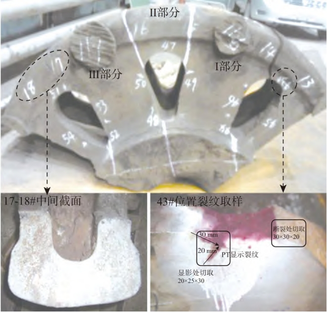
The fracture of the crankshaft occurred at the 7th and 8th cranks. The crack source of the 7th crank was located at the edge of the rolling groove at the intersection of the 7th crank and the 4th connecting rod lower dead center. The crack extended at an angle of approximately 45° to the crankshaft axis and finally fractured instantaneously near the edge of the rolling groove of the 4th main journal. The crack source area was in the form of an elliptical hole with a size of about 3mm x 7mm. The surrounding edges were clear and showed a radial pattern. There was no obvious plastic deformation. The fracture of the 8th crank was a brittle fracture, and the fatigue crack originated from the 4-connecting rod fillet and extended towards the 5th main journal.
3.3 Scanning Electron Microscopy Analysis
Under the SEM, the hole at the crack source of the 7th crank was composed of two small holes with smooth walls. There were several small cracks around the hole, and there were a small amount of friction marks and fatigue stripes at the edge of the hole. The bottom of the hole was dark. EDS analysis showed that the main elements in the dark substance in the hole were C, O, and Fe, indicating the presence of oxidation. The fracture of the 8th crank near the 4-connecting rod fillet showed a “river pattern” under the SEM, indicating a cleavage fracture. In the middle region of the 8th crank, there were both cleavage and dimple features.
3.4 Microstructure Analysis
The graphite around the hole in the 7th crank was more in quantity, evenly distributed, and the spheroidization level was 2, and the graphite diameter size was 6. The microstructure near the hole was composed of lamellar pearlite + a small amount of ferrite + graphite, and the pearlite content was 95%. There was also a layer of dark substance at the bottom of the hole with a thickness of 5 – 10μm. The graphite in the raised area of the 7th crank was severely deformed due to friction and collision during the fracture of the crankshaft. A martensite layer was found on the surface of the raised area after corrosion, indicating severe friction. There were also some irregular holes connected to the surface of the raised area, and the dark substance in the holes also contained C, O, and Fe.
3.5 Performance Testing
The mechanical properties of the crankshaft were tested by cutting a tensile test bar on the 6th crank and taking a hardness sample at the large disc position. The test results are shown in Table 2. The performance test results meet the technical requirements, indicating that the overall performance of the crankshaft material is acceptable, but the presence of defects has a significant impact on the reliability of the crankshaft.
| Item | Yield Strength/MPa | Tensile Strength/MPa | Elongation/% | Hardness(HBW) |
|---|---|---|---|---|
| Found | 521 | 916 | 7.4 | 302 |
| Technical Requirement | ≥460 | ≥820 | ≥4.5 | 250 – 320 |
4. Failure Cause Analysis
4.1 Invasive Air Hole Formation Mechanism
During the solidification of the metal, gases such as water vapor, carbon monoxide, and carbon dioxide generated by the combustion of water, organic matter in the sand mold and sand core invaded the surface layer of the crankshaft casting at the intersection of the 7th crank and the 4th connecting rod lower dead center rolling groove. Since the surface of the casting had begun to solidify and the gas was difficult to flow outwards, while the internal temperature of the casting was high and the metal had good fluidity, with the increase of gas pressure, the gas expanded towards the interior of the metal, forming an elliptical invasive air hole with a larger internal part and a smaller external part.
4.2 Impact of Invasive Air Hole on Crankshaft Performance
The presence of the invasive air hole reduced the effective bearing area of the crankshaft material and caused local stress concentration, which weakened the connection strength of the crankshaft matrix metal and deteriorated the mechanical properties at the defect location, especially reducing the fatigue strength. When the mining vehicle was operating at full load, the stress at the crankshaft journal fillet exceeded the fatigue limit of the defect location, promoting the rapid formation and propagation of fatigue cracks, resulting in the instantaneous fracture of the 7th crank. Subsequently, due to the inertia of the crankshaft, the 8th crank was instantaneously overloaded and also fractured.
5. Improvement Measures
5.1 Control of Gas-Generating Substances in Sand
The content and moisture of gas-generating substances in the molding sand and core sand should be strictly controlled. The sand laboratory should test the volatile content of the molding sand daily. For ductile iron, the volatile content of the molding sand should be controlled within 2.3 – 2.5. If it exceeds the upper limit, the molding sand control room should be notified in time to adjust the sand ratio.
5.2 Optimization of Gas Hole Parameters
The parameters of the automatic gas hole punching machine should be adjusted to increase the depth of the gas holes on the sand mold surface to 30mm from the cavity surface. This can enhance the exhaust capacity of the sand mold and facilitate the rapid discharge of the gas generated during pouring.
5.3 Improvement of Furnace Charge Management
The quality of furnace charge management should be controlled. The furnace charge must be dry and free of rust. During melting, the high-temperature molten iron should be kept still. The electric furnace should be heated to 1500 – 1520°C and the power should be turned off for 3 – 5 minutes. After spheroidization, the number of slag removal operations for the molten iron should be increased from 2 to 3 times to reduce the liquid slag in the molten iron.
6. Conclusion
In this paper, through a comprehensive analysis of the failed QT900-5 ductile iron crankshaft, the cause of the failure was determined to be the invasive air hole at the intersection of the 7th crank and the 4th connecting rod fillet. The formation mechanism of the defect was explained, and corresponding improvement measures were proposed. This research provides important guidance for improving the manufacturing process and quality control of similar ductile iron crankshafts, helping to enhance the reliability and durability of crankshafts and ensure the safe operation of mining vehicles and other equipment. Future research can focus on further optimizing the manufacturing process and exploring more effective defect prevention methods.