
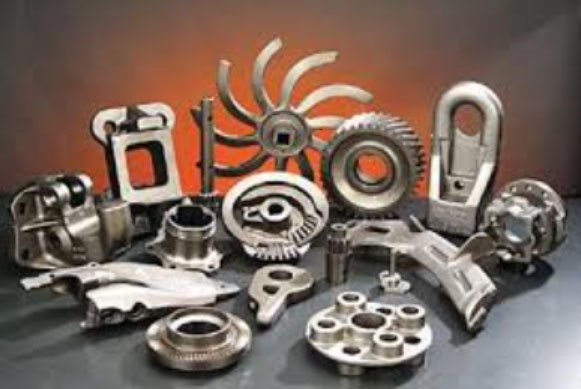
Ductile iron castings are critical components in wind turbine systems, including hubs, main frames, and bearing housings. Their complex geometries and heavy sections (60–120 mm wall thickness) make them prone to shrinkage porosity, a defect that reduces mechanical properties by up to 60% in tensile strength. This article systematically analyzes the root causes and proposes mitigation strategies.
1. Formation Mechanisms of Shrinkage Porosity
The “mushy” solidification behavior of ductile iron casting fundamentally differs from gray iron:
$$ \frac{dT}{dt} = k \cdot \left( \frac{Q_{latent}}{C_p} \right) \cdot \frac{1}{\sqrt{t}} $$
Where T is temperature, t is time, k is a material constant, Qlatent is latent heat, and Cp is specific heat capacity. This equation explains prolonged eutectic solidification in ductile iron casting.
| Wall Thickness (mm) | UTS (MPa) | YS (MPa) | Elongation (%) |
|---|---|---|---|
| ≤30 | 400 | 240 | 18 |
| 30–60 | 390 | 230 | 15 |
| 60–200 | 370 | 220 | 12 |
2. Key Factors Influencing Shrinkage
2.1 Structural Design Challenges
Thick sections (>100 mm) in ductile iron casting create thermal gradients:
$$ \Delta T = \frac{q” \cdot L^2}{2k} $$
Where q” is heat flux, L is section thickness, and k is thermal conductivity. This gradient leads to inverse solidification in heavy sections.
2.2 Mold Material Properties
| Parameter | Acceptable Range | Defect Risk |
|---|---|---|
| Green Strength | 180–220 kPa | High if <150 kPa |
| LOI (Clay Content) | 3.5–4.5% | Shrinkage at >5% |
| Permeability | 80–120 | Gas porosity if <60 |
2.3 Metallurgical Control
The carbon equivalent (CE) for ductile iron casting must satisfy:
$$ CE = C + \frac{Si + P}{3} $$
Optimal CE ranges between 4.3–4.5. Excessive magnesium (>0.06%) increases shrinkage tendency:
$$ V_{shrink} = 0.8 \cdot [Mg]^{1.2} + 0.5 \cdot [RE]^{0.9} $$
Where [Mg] and [RE] represent magnesium and rare earth contents in wt%.
3. Prevention Strategies
3.1 Composition Optimization
| Element | Range (wt%) | Function |
|---|---|---|
| C | 3.75–3.95 | Graphitization |
| Si | 1.8–2.3 | Ferrite Promotion |
| Mg | 0.035–0.06 | Nodularization |
| RE | 0.005–0.015 | Inclusion Control |
3.2 Process Controls
Effective feeding system design follows Chvorinov’s rule:
$$ t_{solid} = B \cdot \left( \frac{V}{A} \right)^n $$
Where B = mold constant (1.0–1.5 for resin sand), V/A = modulus ratio, and n = 1.5–2.0. Proper riser sizing requires:
$$ M_{riser} \geq 1.2 \cdot M_{casting} $$
3.3 Thermal Management
Optimal pouring temperatures for ductile iron casting:
$$ T_{pour} = 1450 – 70 \cdot \log(t_{sec}) $$
Where tsec is section thickness in mm. Chill design follows:
$$ A_{chill} = 0.3 \cdot A_{hotspot} \cdot \sqrt{\frac{k_{chill}}{k_{sand}}} $$
4. Quality Verification
Ultrasonic testing (EN 12680 Class 2) requires:
$$ \Delta Z = 20 \cdot \log \left( \frac{A_{defect}}{A_{ref}} \right) \leq -12 \, \text{dB} $$
Magnetic particle inspection (EN 1369 Class 2) limits defect length to 4 mm maximum.
5. Conclusion
Through integrated control of chemistry, modulus design, and thermal management, shrinkage porosity in ductile iron casting can be reduced by 80–90%. Continuous monitoring of nodularity (≥90%) and ferrite content (≥90%) ensures compliance with wind turbine operational requirements under extreme conditions.