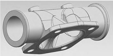
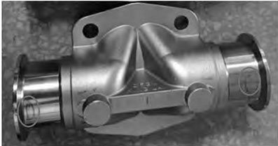
Taking the limit diaphragm valve cartridge body casting as the research object, ProCAST numerical simulation software was used to analyze the initial test plan and optimization improvement plan, and X-ray inspection analysis was carried out on the solid casting. The results showed that after process optimization, the filling of the molten metal was stable, without obvious defects such as insufficient pouring, gas entrapment, and inclusions. The castings also did not show obvious shrinkage porosity defects. The machined castings have a smooth surface, no internal defects, and no leakage after pressure testing. The product quality meets the technical requirements.
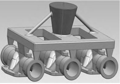
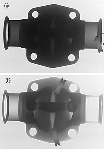
The material used for the casting is 316L stainless steel, and the main technical requirements are: the chemical composition is shown in Table 1. Require the casting to have no casting defects, and after machining, conduct a water medium pressure test at 0.8 MPa pressure to maintain no leakage for 0.5 minutes. According to the shape and characteristics of the limit diaphragm valve cartridge body casting, the initial plan formulated by the enterprise is three pieces of Type 1, as shown in Figure 2. A total of 9 pieces of 3 types were cast in the trial production, and 3 pieces were qualified, with a qualification rate of 33%. The main problem is that there is leakage in the cylindrical part during pressure testing after machining. The position circled by the handwriting in the figure is the leakage location of the machined limit diaphragm valve cartridge body part. Perform X-ray inspection on processed castings using COMMX-RAY, and clearly display photos of defect locations. The reason for this should be that the wall thickness of the tubular parts at both ends of the casting is relatively thin, and it becomes even thinner after processing. If there are slag porosity defects in this area, it is very easy to cause leakage. However, they exist inside the casting and the surrounding wall thickness is relatively large, which is an internal hole and does not affect the leakage performance. The analysis of the initial casting process plan for the limit diaphragm valve cartridge body casting shows that in the initial plan of one type three parts, when pouring starts, the metal liquid directly enters from the middle position of the middle casting. However, the filling sequence of the two symmetrically arranged castings on both sides is that the metal liquid first fills the tubular parts at the two ends of the casting and always maintains a water inlet state, which will seriously hinder the slag and gas floating on the casting at that place. Finally, defects such as slag inclusion and porosity are prone to occur at the circular tube at the upper end of the casting. However, the intermediate castings do not have this problem, and the pouring head is directly filled with shrinkage, making it easy for slag and gas to float up from the set riser, thus reducing the occurrence of slag porosity defects. This also explains the reason for the 33% pass rate of the castings in this scheme.
The distribution of shrinkage holes in the casting shows that the shrinkage holes are mainly concentrated at the two ends and lower part of the castings on both sides. Only the middle diaphragm valve card body casting meets the production requirements, which is consistent with the actual test results. The reason is that the internal gates at both ends have been continuously filled with water and are relatively thin, resulting in poor shrinkage effect of the casting. The shrinkage holes in the lower part are due to the fact that this part is a hot spot, forming small internal shrinkage holes. The simulation analysis of the initial plan also confirmed the correctness of defect analysis from another perspective.
The riser at both ends of the round tube of the casting floats upwards, ensuring a reduction in slag porosity at that location. The solidification time can be analyzed to determine that the casting follows a basic solidification sequence from bottom to top, which is beneficial for ensuring the density of the casting; And the two ends and lower end of the casting solidify almost simultaneously, effectively avoiding the shrinkage force generated on both sides during solidification from affecting the formation of the casting Accuracy has a certain impact, thereby improving the formability of castings. It can be seen that except for the serious shrinkage cavity in the center of the gate, there are no obvious defects in other parts, especially in the initial parts of the casting such as the two ends and lower part, which are prone to defects. Therefore, the improved production plan for the limit diaphragm valve cartridge body casting is significantly better than the initial plan, and the yield has also been greatly improved. The investment casting production of the limit diaphragm valve cartridge body casting was carried out according to the improvement plan. After machining, X-ray perspective inspection was carried out, and there were no defects. The assembly pressure test showed no leakage, meeting the quality requirements.
The study analyzed the defects and causes of the castings produced by the initial scheme of the limit diaphragm valve cartridge body casting, and designed targeted improvement schemes. The ProCAST solidification simulation software was used to analyze the original scheme and optimize the improvement scheme. The production verification results showed that the quality of the limit diaphragm valve cartridge body casting produced according to the improved scheme fully met the technical requirements of the product.