This article takes the failed crankshaft of a four-cylinder engine as the research object. Through theoretical analysis, macroscopic inspection, and microscopic analysis, a comprehensive analysis of the crack source of the crankshaft is conducted, providing certain references for similar crankshaft defect analyses. The main content includes the following: Firstly, through macroscopic examination, it is found that the hole-like casting defect at the intersection of the 7th crank and the 4th connecting rod fillet is the crack source of the crankshaft fracture. Secondly, by using detection equipment such as scanning electron microscopy, metallographic microscope, and energy dispersive spectrometer, a comprehensive analysis of the fracture crack area of the failed crankshaft is carried out, and it is confirmed that the hole is an invasive air hole. Dark substances are detected in the hole, and their main elements are C, O, and Fe. Finally, the formation reasons of the invasive air hole are analyzed, and improvement measures are proposed for the content and moisture content of the gas-generating substances in the molding sand and core sand, the depth of the gas holes, and the management of the furnace materials.
1. Introduction
The ball crankshaft has both the advantages of simple manufacturing and low cost compared to the traditional forged steel crankshaft, as well as excellent characteristics such as shock absorption, wear resistance, and insensitivity to surface notches. It has good matching performance with bearings made of babbitt alloy, lead bronze, and steel back aluminum alloy. Through alloying, proper spheroidization, and inoculation treatment, its fatigue strength under torsional and bending fatigue stress conditions can reach or even exceed that of forged steel crankshafts.
2. Experimental Procedure
2.1 Experimental Instruments
The following instruments are used in the experiment: HX-HW8B high-frequency infrared carbon-sulfur analyzer (Nanjing Huaxin Analytical Instrument Manufacturing Co., Ltd.); Plasma 3000 ICP spectrometer (Sinosteel NCS Testing Technology Co., Ltd.); Hitachi S 3400 N scanning electron microscope (Hitachi, Ltd.); JED-2200 energy dispersive spectrometer (JEOL, Ltd.); Metallographic microscope (Olympus Corporation); E45-305 electronic universal material testing machine (MTS Industrial Systems, Inc.); and THBS-3000DD Brinell hardness tester (Beijing Time Group Inc.).
2.2 Chemical Composition Analysis
The chemical composition test results of the failed crankshaft are shown in Table 1. The determination of C and S is based on the national standard GB 20123-2006 “Determination of total carbon and sulfur content in steel by high-frequency induction furnace combustion infrared absorption method”, while the determination of other elements is based on the national standard GB/T 20125-2006 “Determination of multi-element content in low alloy steel by inductively coupled plasma atomic emission spectrometry”. By comparing the test results in Table 1 with the technical requirements, it can be seen that the chemical composition meets the technical requirements.
3. Test Results and Analysis
3.1 Macroscopic Analysis
The fracture morphology of the failed workpiece shows the failure mechanism and process of the combined action of the load it withstands, its own material, and the operating environment. Usually, the failure of the workpiece starts from the surface or near-surface damage, leaving unique characteristics and traces, including the morphology, metallographic structure, and color changes of the fracture surface. Fracture feature analysis is to find the origin position of the failure fracture, the direction of fracture propagation, and the stress characteristics at the time of failure based on these characteristics and traces on the fracture surface of the failed workpiece, and to confirm whether there are macroscopic defects in the crack source area, and then judge the main crack, crack source, or failure nature, etc.
For the crankshaft with a fracture, the strengthening process is grooving and rolling. Through the rolling strengthening, the tensile stress on the fillet surface becomes compressive stress. The tensile stress is the main factor for the fatigue failure of the crankshaft fillet, while the residual compressive stress on the fillet surface can effectively offset part of the tensile stress during the operation of the crankshaft and reduce the peak stress, thereby greatly improving the fatigue strength of the crankshaft fillet. The fatigue source position of the fillet that is not strengthened by rolling is generally at the center of the fillet with stress concentration, while after the fillet is strengthened by rolling, due to the pressure reduction and peak shift effect of the residual compressive stress, the fatigue source generally shifts to the edge positions on both sides of the rolling groove.
From Figure 2(a) and 2(b), it can be seen that the crack source is also located at the position of the intersection of the 7th crank and the 4th connecting rod’s bottom dead center rolling groove, near the 7th crank surface. The direction of crack propagation is basically at a 45° angle with the axial direction of the crankshaft, and finally, an instantaneous fracture occurs at the position near the 4th main journal fillet rolling groove edge.
By observing the fracture of the 7th crank in Figure 1, it can be seen that the distribution characteristics of the crack source area, propagation area, and instantaneous fracture area in the fracture area are obvious. In order to better observe the fracture morphology of the 7th crank, the area enclosed by the white box in Figure 1 is enlarged, and the enlarged morphology is shown in Figure 2(b).
It can be clearly seen from Figure 2(b) that the crack source area (within the white circle) is located near the surface of the 7th crank arm on the 4th connecting rod side, and the crack source presents a hole-like shape, with an elliptical shape, larger inside and smaller outside, with a size of approximately 3mm x 7mm. The hole has a large volume, is macroscopically obvious, and is very easy to identify. The edge of the hole is distinct, with a radial pattern structure that extends to all sides without obvious plastic deformation [2]. The instantaneous fracture area is at the edge of the crank near the 4th main journal, and the middle part between the two is the propagation area, where there are obvious fatigue propagation lines. The crack extends from around the hole in the crack source area to both sides of the crank arm and one side of the 4th main journal, and finally, an instantaneous fracture occurs on the side of the 4th main journal (as indicated by the arrow in the instantaneous fracture area in Figure 2), and the direction of fracture propagation is indicated by the white arrow in Figure 2(b).
By observing and comparing the two fractures of the 7th crank, it is found that there are obvious differences in the morphology of the two fractures. The crack source morphology of the fracture connected to the 4th main journal presents an elliptical hole-like shape, and the bottom color of the hole is dark; the crack source morphology on the other side connected to the 4th connecting rod neck is slightly outwardly convex, and the convex shape matches the shape of the hole, with relatively severe wear. Judging from the crack source morphology, it clearly belongs to a certain casting defect. In the daily failure analysis of ductile iron workpieces, such radial crack sources can often be found at the positions where casting defects exist, and casting defects can precisely promote and induce the internal failure and fracture of the workpiece. In addition, the macroscopic fracture of the 7th crank is smooth and flat, without obvious plastic deformation, with a bright color and metallic luster, and there are few friction and impact traces on the fracture surface, indicating that the 7th crank fractures rapidly within a short period after the engine is overloaded.
Figure 3 shows the fracture morphology of the 8th crank. By observing the fracture morphology, the fatigue lines originate from the fillet of the fourth connecting rod, and this area is smooth and has a silver-gray color, indicating a brittle fracture. The direction of fracture propagation extends from the 4th connecting rod side to the 5th main journal direction, as shown by the white arrow in Figure 3. The middle fracture surface of the 8th crank is rough and uneven, with a gray surface color, no crystal grains, and no metallic luster. Judging from the fracture morphology, the middle part of the fracture morphology of the 8th crank is a mixed morphology fracture. The position near the 5th main journal of the 8th crank is the final instantaneous fracture area. In addition, there are basically no friction traces on the fracture surface of the 8th crank, indicating that the 8th crank also fractures rapidly within a short period. The macroscopic casting defect analysis and microscopic fracture morphology analysis are carried out on the instantaneous fracture area of the 8th crank to confirm the fundamental cause of the occurrence of the instantaneous fracture area.
It can be seen from the macroscopic fractures of the 7th and 8th cranks that the fatigue fracture of the 7th crank starts from the possible casting defect, being the first fracture; after the fatigue fracture of the 7th crank, it causes an instantaneous overload of the 8th crank within a short period, and then the 8th crank fails and fractures, so the 8th crank is the second fracture.
3.2 Scanning Electron Microscopy Analysis
Figures 4(a), 4(b), and 4(c) show the SEM morphology of the hole area of the 7th crank. Under SEM observation, the hole at the crack source is composed of two small holes, with a smooth hole wall; there are several small cracks around the hole, and there are obvious traces of a small amount of friction and fatigue stripes at the edge of the hole. The bottom area of the hole is dark. To confirm the composition of the dark substances at the bottom of the hole, the energy dispersive spectrometer (EDS) is used to analyze the dark substances at the bottom of the hole, and the specific position is shown in the white box in Figure 4(c). The EDS shows that the main elements of the dark substances in the hole are C, O, and Fe, indicating that there is oxidation in the hole, and the dark substances contain oxides, and the analysis results are shown in Figure 4(d).
Figure 5 is the SEM morphology of the raised area of the 7th crank, from which it can be seen that the raised area at the fracture of the 7th crank is relatively severely worn, and most of the area is a friction trace.
Figure 6 is the SEM morphology of the area near the 4th connecting rod fillet of the 8th crank. According to the national standard GB/T 17359–2012 “Quantitative analysis of energy dispersive spectrometry in microbeam analysis”, the fracture morphology of the area near the 4th connecting rod fillet of the 8th crank under SEM presents a “river pattern”, with obvious cleavage characteristics, being a cleavage fracture. The fracture morphology of the middle area of the 8th crank has both cleavage and dimple features, that is, the coexistence of cleavage and dimples. From the perspective of the 8th crank, there are no obvious casting defects such as shrinkage porosity and pores in the fracture, indicating that the fracture of the 8th crank is caused by an instantaneous overload.
3.3 Microstructural Analysis
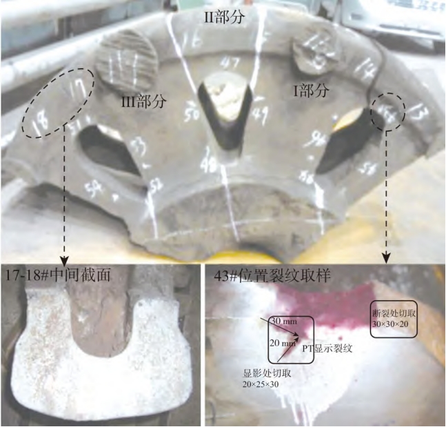
Line cutting is used to cut samples from both sides of the crack source of the 7th crank arm for metallographic and scanning electron microscopy analysis, and the specific sampling positions are shown in the white boxes in Figures 7(a) and 7(b). The cut samples are shown in Figures 7(c) and 7(d).
According to the national standard GB/T 9441–2009 (Metallographic examination of ductile iron), the cross-sectional metallographic structure of the hole area of the 7th crank is detected, as shown in Figure 8. It can be seen from Figure 8 that there are a relatively large number of graphite around the hole, with a relatively uniform distribution and a good spheroidization degree of the graphite. The graphite spheroidization grade is level 2, and the graphite spheroid diameter size is level 6. By using a 5% nitric acid ethanol solution to corrode and observe the sample, it is found that the tissue near the hole consists of lamellar pearlite + a small amount of ferrite + graphite, with a pearlite content of 95%; in addition, a layer of dark substances is also observed at the bottom of the hole, with a thickness of 5-10 μm.
Figure 9(a) is the SEM morphology of the hole sample of the 7th crank. The EDS is used to analyze the dark substances at the bottom of the hole, and the specific position is shown in the white cross in Figure 9(a); the EDS shows that the main elements of the dark substances are also C, O, and Fe, and the specific analysis results are shown in Figure 9(b). From the test results, it can be seen that a layer of oxide is also covered at the bottom of the hole, and no elements such as S and Mg are found, and there is no flake-like graphite around the hole, indicating that there is no problem of slag inclusion.
As shown in Figure 10(a), the cross-sectional metallographic structure of the crack source raised area is as follows. It can be seen from the figure that the surface layer of the raised area has been severely frictionally damaged. It can also be seen from Figure 10(a) that the graphite at the raised position is severely deformed due to the frictional impact and extrusion during the crankshaft fracture, and the graphite morphology changes from a spherical shape to a flake shape, with small and round internal graphite balls away from the surface layer. In addition, a martensite layer is found on the surface layer of the raised area after the sample is corroded, which also indicates that the raised area is subject to severe friction, which is consistent with the SEM findings. From Figure 10(a), there are similar island-shaped irregular holes in the field of view slightly below the surface of the raised area, and these holes are connected to the surface of the raised area through small worm-like holes, and there is also a part of substances in the holes. After corrosion, it is observed that they are also black fillers. The EDS is used to analyze the dark substances at the bottom of the hole, and the analysis position is shown in the white cross cursor in Figure 10(a). The EDS shows that the main elements of the dark substances are also C, O, and Fe, indicating that there are oxides in the holes slightly below the surface of the raised area, and the specific analysis results are shown in Figure 10(b).
3.4 Properties Detection
The tensile test specimens are cut and processed from the 6th crank, and the hardness specimens are taken from the large disk position. The test results are shown in Table 2. It can be seen from Table 2 that the performance test results meet the technical requirements.
4. Analysis and Improvement
Through the macroscopic and microscopic inspections, it is analyzed that the casting defect at the fracture position of the 7th crank is an invasive air hole. In this example, the gas entering the molten metal first generates an elliptical air hole at the subsurface of the intersection position of the 7th crank and the 4th connecting rod’s bottom dead center rolling groove, and then the casting shell begins to cool and solidify, while the gas volume and gas pressure continue to increase. Due to the solidification of the shell, the gas cannot flow outwards, while the internal temperature of the casting is relatively high, the metal fluidity is good, and the resistance is small, so the gas flows to the inside. According to the summary in the “Analysis of Casting Defects” compiled by the American Foundry Association about the defect of invasive air holes: “The gas always flows along the path with the least pressure”, so the gas expands to the inside of the metal, thereby forming a shape that is larger inside and smaller outside.
Based on all the above analyses, the reasons for the crankshaft fracture are as follows:
- Invasive air hole process: Gases such as water vapor, carbon monoxide, and carbon dioxide formed by the combustion of water, organic matter, etc. in the molding sand and core sand invade the surface layer of the crankshaft casting at the intersection position of the 7th crank and the 4th connecting rod’s bottom dead center rolling groove, forming an elliptical invasive air hole.
- The invasive air hole damages the connection strength of the crankshaft matrix metal, deteriorates the mechanical properties at the defect location, and reduces the fatigue strength.
- When the mining vehicle operates at full load, it causes excessive bending and torsional stress near the crankshaft journal fillet, and the stress exceeds the fatigue limit at the defect location of the invasive air hole, promoting the rapid formation and propagation of fatigue cracks, resulting in the rapid fracture of the 7th crank.
- After the fatigue fracture of the 7th crank, the crankshaft continues to rotate due to inertia, resulting in an instantaneous overload of the 8th crank within a short period, and then the 8th crank also fails and fractures instantaneously. At the same time, the rear end of the cylinder block cracks, the 4th connecting rod bends, and the camshaft of the 4th cylinder also fractures.
The analysis results show that the production process of the crankshaft fully meets the requirements, and it is not recommended to make major changes to the process, operation methods, or materials. However, in terms of long-term continuous improvement, the following suggestions are put forward:
- Strictly control the content and moisture content of the gas-generating substances in the molding sand and core sand. The molding sand laboratory detects the volatile content of the molding sand every day, and the volatile content of the ductile iron molding sand is controlled at 2.3-2.5. If it exceeds the upper limit, the molding sand control room will be notified in a timely manner to adjust the molding sand ratio.
2.Adjust the parameters of the automatic air hole pricking machine to increase the depth of the air holes on the surface of the sand mold. The distance from the cavity surface is 30mm, which increases the exhaust capacity of the sand mold, facilitating the rapid discharge of the gas generated during the pouring process.
3.Control the quality of the furnace material management, requiring the furnace materials to be dry and free from rust on the surface; increase the standing time of the high-temperature molten iron during melting, raise the temperature of the electric furnace to 1500-1520°C, and stop the power for 3-5 minutes; increase the number of slag skimming times of the molten iron after spheroidization from the original 2 times to 3 times to reduce the liquid slag in the molten iron.
5. Conclusion
In this article, taking the failed four-cylinder crankshaft as the research object, a comprehensive analysis of the crack source of the crankshaft is carried out by using theoretical analysis, macroscopic detection, and microscopic analysis. The following conclusions are obtained:
- Through macroscopic inspection, it is found that the hole-like casting defect at the intersection of the 7th crank and the 4th connecting rod fillet is the crack source of the crankshaft fracture. By using scanning electron microscopy, metallographic microscope, and energy dispersive spectrometer and other detection equipment to comprehensively analyze the fracture crack area of the failed crankshaft, it is confirmed that the hole is an invasive air hole. Dark substances are detected in the hole, and their main elements are C, O, and Fe.
- The water, pulverized coal, and starch in the molding sand, and the resin, curing agent, and other organic substances in the core sand burn to form water vapor, carbon monoxide, carbon dioxide, and other gases, which invade the surface layer of the casting at the intersection of the 7th crank and the 4th connecting rod’s bottom dead center rolling groove, forming an elliptical invasive air hole.
- This article only makes corresponding improvements to the moisture content of the molding sand and core sand and the quality of the furnace materials, and does not conduct in-depth research on the crankshaft process, operation method, and material, which is also the focus of future research.
Future research can focus on further optimizing the production process of the crankshaft. For example, exploring new materials or additives that can effectively reduce the formation of casting defects. At the same time, more advanced testing techniques can be used to detect potential defects in the crankshaft in real time during the production process, so as to improve the quality and reliability of the crankshaft. In addition, the influence of different operating conditions on the service life of the crankshaft can also be studied to provide more comprehensive guidance for the design and use of the crankshaft.
In conclusion, the research on the defect of the QT900 – 5 ductile iron crankshaft is of great significance for improving the quality of the crankshaft and ensuring the safe operation of the equipment. Through continuous research and improvement, it is expected to effectively reduce the occurrence of similar defects and promote the development of the relevant industry.