
In the realm of heavy-duty engine manufacturing, the cylinder block stands as one of the most critical components. As a foundry engineer specializing in large castings, I have consistently observed that the quality of this grey iron casting is paramount to the overall performance, durability, and reliability of the entire engine. Among the various defects that can plague production, cracking is particularly detrimental and prevalent in high-grade grey iron castings such as those made from HT300. These cracks severely compromise mechanical properties and structural integrity. This article details a first-hand investigation into the root causes of persistent crack defects in a specific series of large marine diesel engine blocks and outlines the systematic, multi-faceted approach we implemented to resolve them.
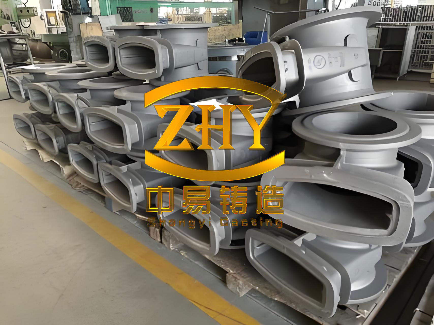
The subject of this study is a substantial grey iron casting. The block has a rough casting dimensions of 4,060 mm in length, 1,670 mm in width, and 1,250 mm in height, with a weight approximating 12 tonnes. The material specification is HT300, a high-strength grade of grey iron, which inherently presents challenges due to its sensitivity to cooling stresses. A primary challenge in producing this grey iron casting lies in its extreme variation in wall thickness. While the nominal wall thickness is around 15 mm, certain sections, like the main bearing supports, can reach up to 170 mm. This significant disparity creates inherent thermal gradients during solidification and cooling, a classic problem in complex grey iron casting. It is well-established that such non-uniform sections generate substantial internal stresses, dramatically increasing the susceptibility to crack formation. The complex internal geometry, featuring numerous ribs, galleries, and observation windows, further complicates stress distribution in this massive grey iron casting.
The production process for this grey iron casting utilized an alkaline phenolic resin no-bake sand system for molding and core-making. The molds were assembled manually, including core setting and closing. The gating system was designed as a horizontal pour with a reverse rain-style setup employing ceramic tubes. A notable feature was that the main oil gallery was not cast but machined in a subsequent operation. The pouring temperature was carefully controlled between 1,390°C and 1,410°C. After pouring, the casting was allowed to cool in the mold for a period of four days before shakeout, followed by a stress relief annealing treatment.
Despite this controlled process, a severe defect emerged consistently. Upon shakeout, a crack was found at the fillet radius of the first observation window on the front face of the cylinder block. The reject rate soared to an unacceptable 35%. The crack originated at the external fillet of the window and propagated inwards in a jagged, linear pattern, terminating near the root of an internal rib. The crack width was most severe at the outer surface and diminished towards the interior, a key morphological clue.
Defect Classification and Root Cause Analysis
The first step was to correctly classify the defect. Casting cracks are broadly categorized as either hot tears or cold cracks. Understanding the distinction is crucial for identifying the correct root cause in a grey iron casting.
- Hot Tear: Forms in the late stages of solidification or immediately after, while the metal is still at a high temperature and has very low strength and ductility. It results from hindered contraction during this vulnerable state. Characteristically, the fracture surface is heavily oxidized, lacks metallic luster, and appears as a ragged, irregular line.
- Cold Crack: Develops when the casting has fully solidified and cooled to a lower temperature where it has entered the elastic state. It is caused by local stress exceeding the material’s tensile strength. The fracture surface is typically clean, smooth, or lightly oxidized, and the crack path is often straight or sharply angular.
The observed crack—with its relatively smooth appearance, angular propagation, and surface origin—clearly fit the definition of a cold crack in this grey iron casting. This diagnosis directed our investigation towards factors causing high residual stress and stress concentration during the cooling phase.
The core of the problem was identified as a consequence of non-simultaneous solidification and contraction, exacerbated by geometric stress concentrators. In the original design, the area around the observation window was relatively thin-walled compared to the massive section housing the main oil gallery. To prevent shrinkage porosity in this thick oil gallery section, a feeding riser had been placed above it. This created a severe thermal disparity:
- The thin observation window area solidified and began to cool and contract first.
- The thick oil gallery section, kept “hot” longer by the riser, solidified and started its significant contraction much later.
- As the oil gallery region finally contracted, it pulled on the already cool and rigid window area, placing it under high tensile stress.
This tensile stress was amplified at the sharp fillet radius (R20) of the observation window. Stress ($\sigma$) concentration at a notch or fillet can be described conceptually by the stress concentration factor $K_t$:
$$\sigma_{max} = K_t \cdot \sigma_{nominal}$$
Where a sharp radius results in a very high $K_t$, leading to a localized stress ($\sigma_{max}$) far exceeding the nominal stress in the grey iron casting. When $\sigma_{max}$ surpasses the fracture strength of the brittle grey iron at that temperature, a cold crack initiates.
Furthermore, the four-day in-mold cooling period, while standard, might have been insufficient for such a massive grey iron casting. A high shakeout temperature means the casting possesses greater residual thermal stress and is more susceptible to damage from mechanical impact during handling and cleaning, potentially providing the final trigger for crack propagation.
| Feature | Hot Tear | Cold Crack |
|---|---|---|
| Formation Temperature | High (Near solidus) | Low (Elastic range) |
| Mechanism | Hindered contraction in mushy/low-strength state | Local stress > Tensile strength |
| Fracture Appearance | Oxidized, ragged, intergranular | Clean/smooth, transgranular, straight/angular |
| Typical Location | Hot spots, junctions | Stress concentrators (sharp corners) |
| Primary Cause in this Grey Iron Casting | Not Applicable | Thermal stress + Stress concentration + Early shakeout |
A Multi-Pronged Solution Strategy
Resolving cold cracks in a complex grey iron casting like this required a holistic approach targeting stress reduction, stress redistribution, and strength enhancement at critical points. We implemented four interconnected modifications.
1. Product Structure Optimization for Stress Reduction: The most direct intervention was to modify the geometry of the grey iron casting itself (within assembly constraints).
- The sharp R20 fillet at the observation window was radically increased to R80. This simple change dramatically reduces the stress concentration factor $K_t$, dispersing the tensile stress over a larger area and lowering $\sigma_{max}$ below the critical threshold for crack initiation. The relationship between fillet radius (r) and stress concentration is inversely proportional; increasing r is one of the most effective ways to improve the durability of a grey iron casting.
- Internal ribs around the window were connected to create a more continuous and rigid framework. This improves the overall stiffness of the window area, better resisting deformation from contraction pulls.
- A strategic connecting rib was added between the heavily-fed oil gallery section and the problematic window area. This fundamentally altered the solidification dynamics. It effectively opened a “thermal channel,” allowing some of the feeding effect from the riser to extend towards the window zone. This promoted a more balanced temperature field, reducing the severe thermal gradient that was the root cause of the high tensile stress. The goal was to move closer to the principle of directional or balanced solidification, even locally, in this intricate grey iron casting.
2. Application of Anti-Crack Reinforcement: To immediately bolster the weakest point, we designed and added a temporary external reinforcing rib across the observation window opening. This rib featured a pre-defined, shallow notch (a “break-off” groove) at its center. The principle here is ingenious: the notch creates a controlled, weakest point. During cooling, when tensile stresses build up, they are preferentially concentrated and released at this designed notch through minor deformation or micro-cracking, thereby “sacrificing” the temporary rib and protecting the actual grey iron casting from cracking. This sacrificial rib was removed after the stress relief heat treatment.
3. Process Adjustment for Lower Residual Stress: We revised the cooling protocol to allow for more gradual and uniform stress relaxation within the grey iron casting.
- The in-mold cooling time was extended from 4 days to 5 days. This allows the thick and thin sections to reach a more uniform temperature before being exposed to the ambient air, minimizing thermal shock and the final locked-in stress state. The sand mold acts as an excellent insulator, promoting slow cooling.
- Mold clamping devices were loosened at an earlier stage (after the initial solidification but during the in-mold cooling). This small step is critical as it reduces external mechanical restraint on the contracting grey iron casting, allowing it to shrink more freely and further lowering residual stress.
The combined effect of these measures can be conceptually summarized by modifying the basic stress equation for the failure condition. The original scenario leading to crack formation was:
$$\sigma_{thermal} \cdot K_t(r_{small}) + \sigma_{restraint} > \sigma_{UTS}(T_{shakeout})$$
Where $\sigma_{thermal}$ is the thermal stress from the gradient, $K_t$ is the high concentration factor from the small radius, $\sigma_{restraint}$ is stress from mold/core restraint, and $\sigma_{UTS}$ is the material’s ultimate tensile strength at the shakeout temperature. Our interventions changed this inequality:
$$\frac{\sigma_{thermal}^{‘}}{\text{(reduced by balanced cooling)}} \cdot K_t^{‘}(r_{large}) + \frac{\sigma_{restraint}^{‘}}{\text{(reduced by longer cooling/loose molds)}} < \sigma_{UTS}^{‘}(T_{lower}) + \sigma_{reinforcement}^{‘}$$
The thermal and restraint stresses are reduced, the stress concentration factor is lowered, the material strength is higher at a lower shakeout temperature, and the reinforcement provides an additional safety margin.
| Corrective Action | Primary Effect | Mechanism/Principle |
|---|---|---|
| Increase Fillet Radius (R20 to R80) | Reduces Stress Concentration | Lowers the stress concentration factor $K_t$, dispersing localized stress. |
| Add Connecting Ribs | Promotes Balanced Solidification | Improves thermal connectivity, reduces thermal gradient and associated stress. |
| Apply Sacrificial Reinforcing Rib | Provides Local Strength & Stress Relief | Acts as a stiffener and creates a controlled point for stress relief, protecting the main casting. |
| Extend In-Mold Cooling (4 to 5 days) | Lowers Overall Residual Stress | Allows for more uniform temperature, reducing thermal stress before shakeout. |
| Loosen Molds Earlier | Reduces Mechanical Restraint | Minimizes hindrance to free contraction of the grey iron casting. |
Results and Conclusion
The implementation of this integrated solution package proved highly successful. Following these modifications, over fifty cylinder blocks of this series were produced. Each grey iron casting was subjected to rigorous non-destructive testing, including dye penetrant inspection, after initial cleaning. The result was a complete elimination of the cracking defect at the observation window location. The reject rate related to this issue dropped from 35% to effectively 0%, yielding significant cost savings and reliability improvements for this high-grade grey iron casting.
This case study underscores a fundamental lesson in producing heavy-section, high-strength grey iron castings: crack defects, particularly cold cracks, are seldom attributable to a single cause. They are the product of a confluence of factors—design geometry, thermal history, and mechanical restraint. Therefore, an effective resolution demands a systemic approach. The strategy must encompass:
- Design for Manufacturability: Product designers should aim for uniform wall thicknesses and generous fillet radii to minimize stress concentration in the grey iron casting from the outset.
- Principles of Solidification Control: Foundry process design must strive for thermal balance, using chills, risers, and padding not just to prevent shrinkage but also to manage cooling sequences and minimize stress-inducing gradients.
- Optimization of Production Practice: Foundry floor practices, such as adequate in-mold cooling times, early removal of restraints, and gentle handling of hot castings, are not minor details but critical factors in preventing stress-related failures in grey iron casting.
By addressing the issue through simultaneous optimization of the product structure, the feeding and cooling methodology, and the post-pouring handling procedure, we developed a robust and reliable manufacturing process for this challenging high-grade grey iron casting. The principles applied here—of analyzing stress states, modifying geometry to disperse stress, and controlling the thermal regime—are universally applicable to preventing cold cracks in complex and heavy grey iron castings across the industry.