
1. Introduction
Casting quality, as defined in GB/T5611 casting terms, refers to various defects on the surface and inside of the casting during the production process. This article focuses on analyzing the “shrinkage and leakage” defects on the machining surface of a casting and proposes targeted solutions to improve the casting pass rate and reduce waste loss.
1.1 Shrinkage Defects
- Shrinkage Hole: Irregularly shaped holes with rough walls and dendritic crystals, often occurring in the last solidifying part of the casting due to poor feeding during solidification.
- Shrinkage Porosity: Dispersed and fine shrinkage holes on the casting cross-section. Microscopic shrinkage porosity requires a high-power magnifying glass to be detected. Castings with shrinkage porosity are prone to leakage during airtightness tests.
- Looseness: Fine holes in the slow solidification area of the casting, distributed within and between dendrites, a combination of dispersed pores, microscopic shrinkage porosity, and coarse structure, reducing the casting density and causing leakage.
- Leakage: Gas, water, or oil leakage during airtightness tests or in use, often caused by shrinkage porosity, looseness, coarse structure, capillary cracks, pores, or inclusions in the casting.
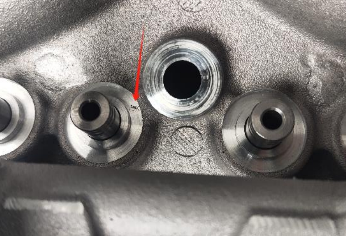
2. Introduction and Analysis of Physical Defects
The HQ21312 product of our company has a leakage problem in the cavity exhaust side during the water cavity airtightness test after processing, with a leakage ratio of 4.35%. Additionally, about 7.75% of the casting defects occur on the processing platform of the second and third cylinder exhaust side duct holes.
| Defect Location | Defect Phenomenon | Defect Ratio |
|---|---|---|
| Cavity Exhaust Side | Leakage in Water Cavity Airtightness Test | 4.35% |
| Second and Third Cylinder Exhaust Side Duct Hole Processing Platform | Casting Defects, Leakage in Waterway Airtightness Test | 7.75% |
2.1 Defect Analysis Results
- Ray Detection Results: The defect parts were dissected and ray detected, revealing shrinkage porosity defects, including both penetrating and isolated ones. Penetrating shrinkage porosity led to leakage after machining, and some non-penetrating defects were removed during machining.
- Metallographic Analysis Results: The metallographic analysis of the dissected samples showed “shrinkage hole and shrinkage porosity” casting defects. The “penetrating holes” caused leakage during the airtightness test.
3. Root Cause Analysis
The defect area is at the bottom of the oil chamber duct hole base processing plane, surrounded by sand cores. This isolated thick part is the last to solidify, resulting in shrinkage porosity and shrinkage hole defects due to the lack of feeding.
4. Solutions
- Adding Feeding Risers: A feeding riser was added above the duct hole platform to directly feed the duct hole area, shifting the solidification hot spot into the riser, ensuring the casting’s thick part is dense and free of casting defects after machining.
- Adding “Cold” to the Mold (if applicable): If the shrinkage-prone thick part is at the bottom of the casting, adding “cold” to the mold can accelerate its cooling rate, achieving sequential solidification and preventing shrinkage porosity and shrinkage hole defects.
5. Machining Verification after Product Improvement
- X-ray Detection Results: After adding the feeding riser and dissecting the casting for X-ray detection, the duct hole area was found to have a dense structure with no shrinkage porosity or shrinkage hole defects, and no leakage occurred during the airtightness test.
- Metallographic Analysis Results: The microscopic structure was dense, with no shrinkage porosity or shrinkage hole defects. The secondary dendrite arm spacing, porosity, and hole diameter all met customer requirements.
| Detection Project | Technical Requirement | Actual Measurement |
|---|---|---|
| Secondary Dendrite Arm Spacing | <28um | 21um |
| Porosity | Average Content < 0.30% | 0.22% |
| Hole | <0.10mm | 0.04mm |
| Matrix Structure | Metamorphism 1 – 4 Levels | Metamorphism 2 Levels |
6. Conclusion
Adding feeding risers to areas with shrinkage porosity and shrinkage holes is a common solution. However, the position and size of the riser need to be carefully considered, as well as the removal method, to ensure the product structure meets customer requirements while reducing casting defects and costs. In production, specific problems should be analyzed to optimize the casting process and improve casting quality.