
In my daily work at a foundry specializing in diesel engine components, green sand (clay-bonded sand) is the primary molding material. It consists of silica sand, bentonite, coal dust, starch, and water. This method accounts for 60–70% of all sand casting processes due to its low cost and short production cycle. However, the inherent weaknesses of green sand—low strength, low hardness, poor toughness, and high gas evolution—frequently lead to several typical sand casting defect types: sand holes, gas porosity, sand inclusions, and sand sticking. Over the years, I have systematically analyzed these defects and implemented corrective actions, reducing our overall scrap rate from about 8% to 4–5%. This article summarizes my findings and practical solutions, emphasizing the importance of raw material control, process discipline, and continuous monitoring.
Our production line uses a frequency‑converted rotor mixer with automatic online detection. Old sand is cooled by multiple water sprayers on the conveyor belt. Sand temperature must not exceed 10–15 °C above ambient to avoid hot‑sand problems. Due to a multi‑variety, small‑batch production mode (flywheels, flywheel housings, small complicated parts like bent pipes, simple pulleys), the demands on green sand properties are extremely high.
1. Production Overview and Defect Statistics
Before improvement, the overall scrap rate was about 8%. Among all defects, those directly related to sand casting defect issues accounted for the majority: sand holes, gas porosity, sand inclusions, and sand sticking. Table 1 summarizes the initial defect distribution before corrective actions.
| Defect Type | Percentage of Total Scrap (%) | Primary Cause |
|---|---|---|
| Sand holes | 25 | Low mold strength, loose sand, improper core setting |
| Gas porosity | 35 | Excessive moisture, high gas evolution, poor venting |
| Sand inclusions | 20 | Thermal expansion, low hot‑wet tensile strength |
| Sand sticking | 20 | Low refractory, coarse sand, high pouring pressure |
Table 1: Typical sand casting defect distribution before process improvements.
2. Detailed Defect Analysis
2.1 Sand Holes
Sand holes form when loose sand from the mold surface or core falls into the cavity and becomes entrapped in the metal. The root causes include insufficient green compression strength of the sand, excessive moisture or gas‑producing materials that cause expansion and spalling, uneven ramming density, careless mold repair, and collision during core setting or mold closing. In our plant, sand holes were particularly problematic for small complex parts with thin sections and deep cavities.
2.2 Gas Porosity
Gas porosity is the most frequent sand casting defect in green sand processes, accounting for over one‑third of all scrap. The main gas source is moisture in the sand, but also coal dust decomposition, resin from cores, and dissolved gases in the molten iron. Inadequate venting, excessive mold hardness, improper gating system design, and wet charge materials all contribute.
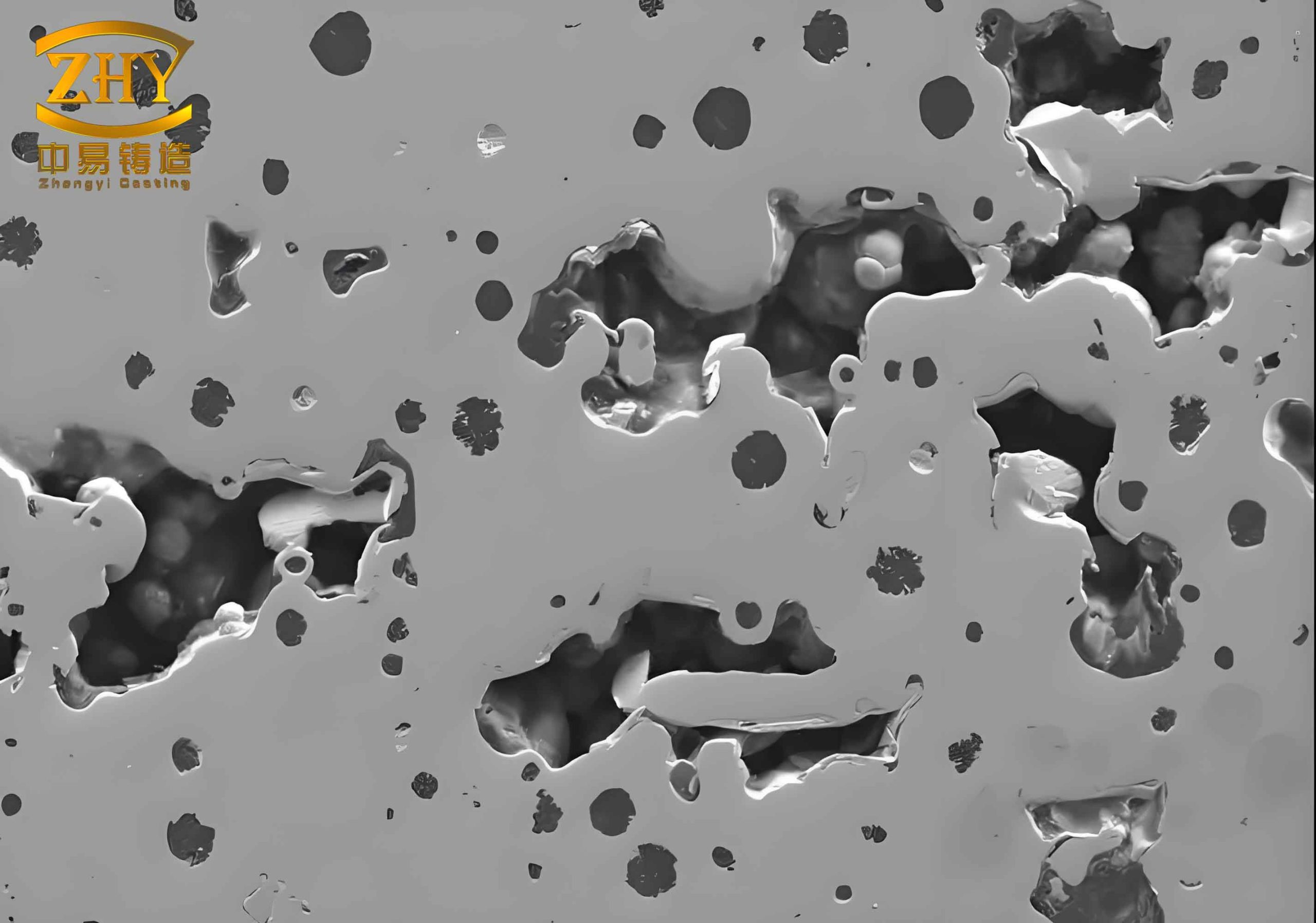
2.3 Sand Inclusions (Expansion Defects)
Sand inclusions, also called scabs or buckle defects, occur when the mold surface expands under thermal shock, causing a layer to peel off. This is especially common on large flat surfaces. Low thermal conductivity, insufficient hot‑wet tensile strength, and non‑uniform expansion are the key factors. The defect appears as a raised layer of sand embedded in the casting surface.
2.4 Sand Sticking
Sand sticking can be mechanical (metal penetrating into sand pores) or chemical (formation of low‑melting compounds like iron silicate). Low silica content, coarse sand grains, high pouring temperature, and excessive metalostatic pressure worsen the problem. Chemical sticking is difficult to remove and severely affects surface quality.
3. Root Cause Analysis Using Quantitative Parameters
To systematically address these sand casting defect issues, I established control limits for key sand properties based on extensive production trials. Table 2 lists the target ranges and their relationship to each defect.
| Property | Symbol/Unit | Target Range | Impact on Defect |
|---|---|---|---|
| Green compression strength | $$ \sigma_{gc} \ (\text{MPa}) $$ | 0.11 – 0.16 | Sand holes (low → more holes) |
| Compactability (CB value) | $$ \text{CB} \ (\%) $$ | 32 – 36 | Gas porosity (high moisture → more gas) |
| Moisture content | $$ w \ (\%) $$ | 3.2 – 3.8 | Gas porosity (direct) |
| Permeability | $$ P \ (\text{cm}^3/\text{min}) $$ | 100 – 140 | Gas porosity & sand sticking (trade‑off) |
| Hot‑wet tensile strength | $$ \sigma_{ht} \ (\text{kPa}) $$ | ≥ 2.5 | Sand inclusions (low → expansion defects) |
| Loss on ignition (LOI) | $$ \text{LOI} \ (\%) $$ | 3 – 5 | Gas porosity & sand sticking (too high → gas; too low → sticking) |
| AFS grain fineness | $$ \text{AFS} $$ | 50 – 100 (83% retained) | Sand sticking (coarse → mechanical penetration) |
Table 2: Key sand properties and their target ranges for controlling sand casting defect occurrences.
The compactability–moisture ratio is a critical indicator. I defined it as:
$$ R = \frac{\text{CB} (\%)}{w (\%)} $$
For our sand, the ideal range is 10–12. If \(R < 10\), the sand is too wet and has poor toughness, increasing gas porosity. If \(R > 12\), the sand is too dry and becomes sensitive to moisture variations, leading to sand holes and inclusions.
4. Preventive Measures
4.1 Solutions for Sand Holes
- Increase green compression strength: For heavy parts like flywheels, target the upper limit (0.16 MPa); for small parts, use lower limit (0.11 MPa).
- Uniform ramming: Achieve mold hardness ≥85 on side walls and 90–92 on flat surfaces. Use pneumatic rammers for vertical walls.
- Core print design: Increase taper angle from 5° to 10°; ensure gap between core print and mold is at least 0.5 mm per side (1 mm if coating is applied). Avoid sharp angles (<90°).
- Careful mold closing: Use dual‑speed hoist control, slow final approach to prevent sand crushing.
- Optimized gating: Reduce direct impingement of molten metal on mold walls.
4.2 Solutions for Gas Porosity
- Moisture control: Maintain CB between 32% and 36%, adjusting seasonally (lower in autumn/winter and on humid days).
- Gas‑evolving additives: Keep LOI within 3–5%. High coal dust addition increases gas evolution.
- Permeability balance: Set permeability to 100–140; lower values increase gas porosity, higher values cause mechanical sand sticking.
- Venting: Add vent holes on the cope, and use ignition rods to burn off gases during pouring.
- Charge material: Dry all furnace charges and ladles; degas molten iron if hydrogen content is high.
4.3 Solutions for Sand Inclusions
- Bentonite selection: Use sodium‑activated bentonite to achieve hot‑wet tensile strength ≥2.5 kPa.
- Coal dust addition: Normally 50% of bentonite weight; increase to 80% for large flat castings prone to expansion. LOI must stay ≤5%.
- Pouring technique: Increase pouring speed to reduce heat‑soaking time. Use inclined pouring (3–15°) for large flat surfaces.
- Mechanical reinforcement: Insert small nails flush with the mold surface on large planes to anchor the sand.
4.4 Solutions for Sand Sticking
- Grain size correction: When sand becomes coarse due to core sand mixing (e.g., cold‑box cores with AFS 50–100), add 100–200 mesh fine new sand to keep AFS distribution within 50–140 mesh (4‑sieve distribution). Permeability should drop from 160–190 back to 100–140.
- Coal dust optimization: LOI 3–5% is ideal. A bluish surface on castings indicates excessive coal dust (LOI >5.3%).
- Pouring pressure: Keep pouring height moderate; excessive pressure increases mechanical penetration.
- Pouring temperature: For thin‑wall parts: 1420–1320 °C; for thick‑wall parts: 1380–1300 °C.
- Mold coating: Apply a fast‑drying refractory coating on mold surfaces. Avoid torching to prevent surface drying that leads to sand holes.
5. Results: Scrap Rate Reduction
After implementing these measures over six months, we observed a significant decline in all sand casting defect categories. Table 3 shows the before‑and‑after comparison.
| Month | Before Improvement (%) | After Improvement (%) |
|---|---|---|
| Month 1 | 8.2 | 6.5 |
| Month 2 | 8.0 | 5.8 |
| Month 3 | 7.9 | 5.2 |
| Month 4 | 8.1 | 4.8 |
| Month 5 | 8.3 | 4.5 |
| Month 6 | 7.8 | 4.2 |
Table 3: Monthly scrap rate trend showing reduction of sand casting defect‑related rejects.
The overall average scrap rate dropped from ~8% to 4–5%, yielding substantial cost savings and improved customer satisfaction.
6. Conclusions
Through rigorous root‑cause analysis and methodical control of green sand properties—especially moisture, compactability, permeability, hot‑wet tensile strength, and loss on ignition—I successfully reduced the incidence of sand holes, gas porosity, sand inclusions, and sand sticking. Key actions included:
- Re‑defining target ranges for each sand property using statistical data.
- Implementing automatic online monitoring and feedback control.
- Training operators on proper mold preparation, core setting, and pouring parameters.
- Introducing corrective additives (fine sand, extra coal dust) as needed.
These measures cut the overall scrap rate by nearly half, demonstrating that a systematic approach to sand casting defect prevention is both effective and economically viable.