In order to cut the area with casting defects in the casting diaphragm, it is necessary to first understand the characteristics of the casting diaphragm defect area, including the size, distribution, depth, etc. of the defect area. The inspection shows that in the casting defect area of the diaphragm, the closer to the surface, the more defects are, and the more inward, the fewer defects are. The defect distribution depth is less than 10 mm, and there are basically no defects below the depth of 10 mm. From the point of view of reducing defects, the greater the cutting thickness, the less material defects of the remaining structure. From the perspective of structural performance, with the increase of cutting thickness, the thickness of the right wall of the cavity of the casting diaphragm gradually decreases, which will increase the stress and deformation of the casting diaphragm, thus increasing the risk of structural rubbing and damage. In order to determine the appropriate cutting thickness, first analyze the stress and deformation of the casting diaphragm under different cutting thickness, and then analyze the improvement of the stress and deformation of the casting diaphragm after repair welding. The stress and deformation results of different cutting/repair welding thicknesses of cast diaphragms are summarized in the table.
| Cutting/repair welding thickness (mm) | 0 | 5 | 10 | 15 | 20 | 25 | 30 | 35 |
| Cutting stress | 215 | 220 | 221 | 222 | 226 | 236 | 247 | 679 |
| Cutting radial deformation | 0.070 | 0.072 | 0.075 | 0.079 | 0.083 | 0.087 | 0.088 | 0.095 |
| Cutting axial deformation | 0.79 | 0.81 | 0.83 | 0.86 | 0.89 | 0.93 | 1.04 | 2.69 |
| Repair welding stress | 215 | 215 | 214 | 210 | 220 | 217 | 228 | 240 |
| Repair welding radial deformation | 0.070 | 0.073 | 0.076 | 0.080 | 0.082 | 0.082 | 0.081 | 0.079 |
| Repair welding axial deformation | 0.79 | 0.81 | 0.83 | 0.85 | 0.87 | 0.88 | 0.88 | 0.89 |
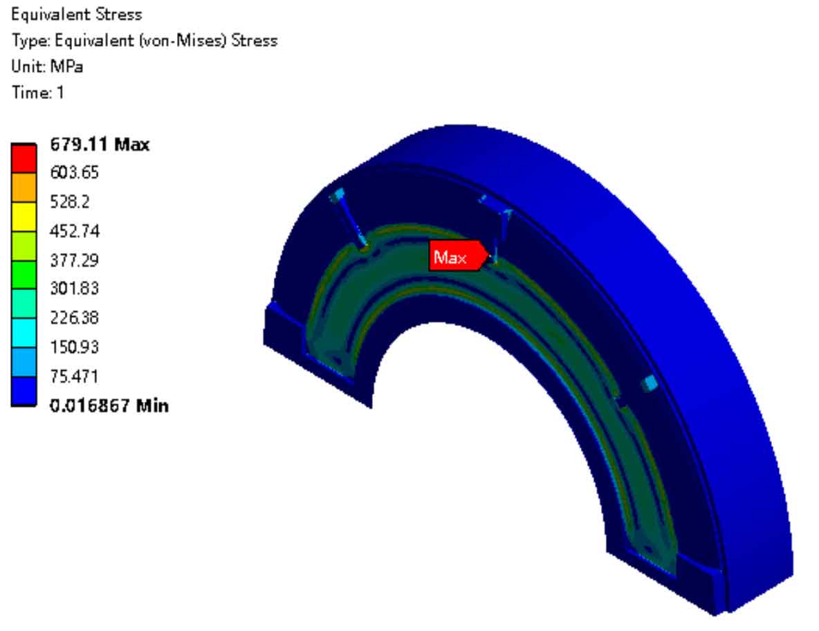
It can be seen from the analysis results after the cutting of cast diaphragms that the stress, radial deformation and axial deformation of cast diaphragms increase with the increase of cutting thickness. During the process of cutting thickness from 5 mm to 30 mm, the increase of stress, radial deformation and axial deformation of cast diaphragms is relatively stable, and the location and distribution of the maximum value are basically the same as those of cast diaphragms in the uncut state. When the cutting thickness of the casting diaphragm is 35mm, the stress and axial deformation of the casting diaphragm increase sharply, and the maximum stress position also changes, from the intersection of the seam and the rib plate to the intersection of the right wall of the cavity and the rib plate, as shown in the figure. This is because the right wall of the cavity is too thin, resulting in excessive local stress.

Evaluate the stress, radial deformation and axial deformation analysis results of the cast diaphragm after cutting. The stress should be less than the material yield limit. Whether the radial deformation meets the requirements depends on the clearance between the mouth ring seal and the impeller. The upper limit value of the radial deformation in this unit is 0.1mm. Therefore, the radial deformation can meet the operating requirements for all cutting thicknesses. Whether the axial deformation meets the requirements depends on the clearance between the casting diaphragm and the impeller. For this unit, the axial deformation of the casting diaphragm is required to be less than 1mm. The evaluation of stress, radial deformation and axial deformation is shown in the vertical line of the table, and the left side of the vertical line is the qualified area. Based on the three analysis results, it can be determined that when the cutting thickness of the casting diaphragm is not more than 20mm, repair welding is not required, and the requirements for safe operation of the casting diaphragm can still be met. However, considering that the casting diaphragm also plays a role in building the flow channel, it is still necessary to repair the casting diaphragm.
By observing the analysis results of cast diaphragms after repair welding, it can be seen that the stress of cast diaphragms generally presents an upward trend. In the structure with repair welding thickness of 10mm and 25mm, the stress has slight fluctuations, which is caused by the calculation deviation caused by different cutting thickness of cast diaphragms, resulting in different overall grids of the structure. By observing the analysis results of cast diaphragms after repair welding in the table and combining the three evaluation results, it can be determined that when the cutting thickness of cast diaphragms is not more than 30mm, the cast diaphragms after repair welding can meet the requirements of safe operation.
