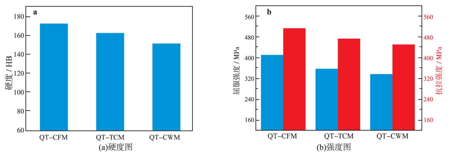
Fig. 1 (a) and Fig. 1 (b) show the hardness and strength changes of three groups of nodular cast iron samples respectively. It can be seen from the figure that the change trend of both hardness and strength (including yield strength and tensile strength) is qt-cfm > qt-tcm > qt-cwm. With the increase of the number of graphite balls, the diameter of graphite balls decreases, and the hardness and strength of three groups of nodular cast iron samples gradually decrease. Qt-cwm has the lowest hardness, yield strength and tensile strength, which are 12.5% lower than qt-cfm 2% 、18. 76% and 12 45% 。
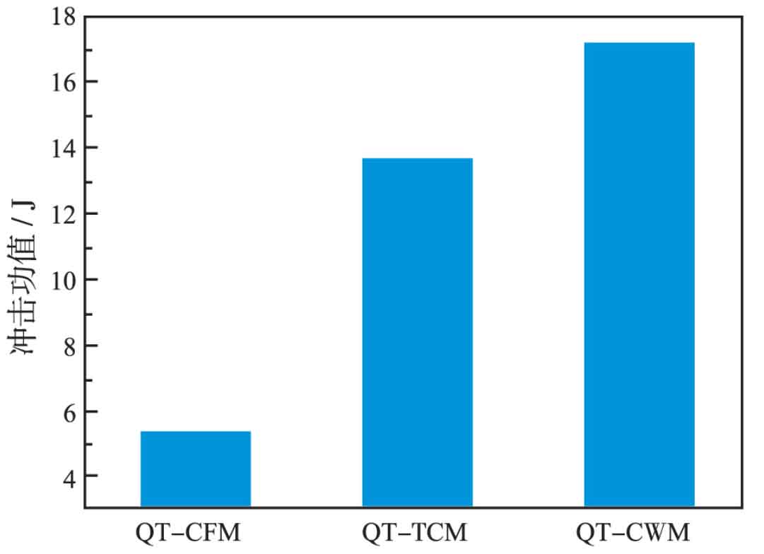
The impact energy value reflects the impact toughness of the material. The higher the impact energy value, the better the impact toughness of the material. Figure 2 shows the low temperature impact energy values of three groups of materials at – 25 ℃. It can be seen from the figure that the impact properties of the three groups of ductile iron samples are quite different, which is just opposite to the change trend of hardness and strength. The minimum impact energy value of qt-cfm is 5 The impact energy values of 3 J, qt-tcm and qt-cwm are 13.5% respectively 7 J and 17 3 J, 158.5% higher than qt-cfm 4% and 203 5%, which shows that refining the diameter of graphite and improving the spherical regularity of graphite ball can greatly improve the impact toughness at low temperature.
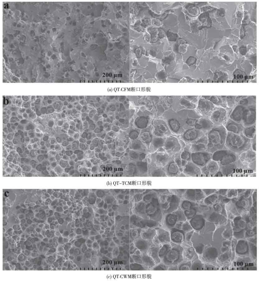
In order to reveal the impact fracture mechanism from the perspective of microstructure, the fracture morphology of different ductile iron samples is analyzed, and the corresponding SEM diagram is shown in Fig. 3. It can be seen from 3 (a): there are few dimples in the ferrite matrix structure of qt-cfm fracture, mainly showing continuous and discontinuous river like cleavage fracture, with obvious cleavage steps, and a small number of tear pits on the cleavage fracture. Part of graphite falls off in the process of impact deformation, forming corresponding holes, and there are obvious entanglement and tear edge structures near the holes. Part of the graphite remains on the original fracture and adheres to the matrix ferrite during impact deformation. There is no obvious tear mark around, indicating that the resistance to crack initiation and propagation is small. Therefore, qt-cfm is mainly brittle fracture.
It can be seen from figures 3 (b) and 3 (c) that during the impact deformation process of QT-TCM and qt-cwm, the gap between the residual graphite ball and the matrix ferrite wall is large, and the matrix ferrite has obvious plastic deformation, which hinders the crack propagation. Part of the graphite falls off and forms corresponding holes, and obvious entanglement and tear edge structures and dimple structures of different sizes are produced near the holes. The fracture of ductile iron sample has a small amount of river like cleavage fracture and obvious cleavage steps. Therefore, the fracture mode of QT-TCM and QT-CWM is a mixed fracture mode of plastic fracture (dimple structure) + brittle fracture (River cleavage fracture), and the plastic fracture mode is the main mode. Compared with QT-TCM, QT-CWM ductile iron sample has more dimples around the cavity, and the gap between the graphite ball retained at the source port and the matrix is large, so QT-CWM has higher low-temperature toughness than qt-tcm.


