
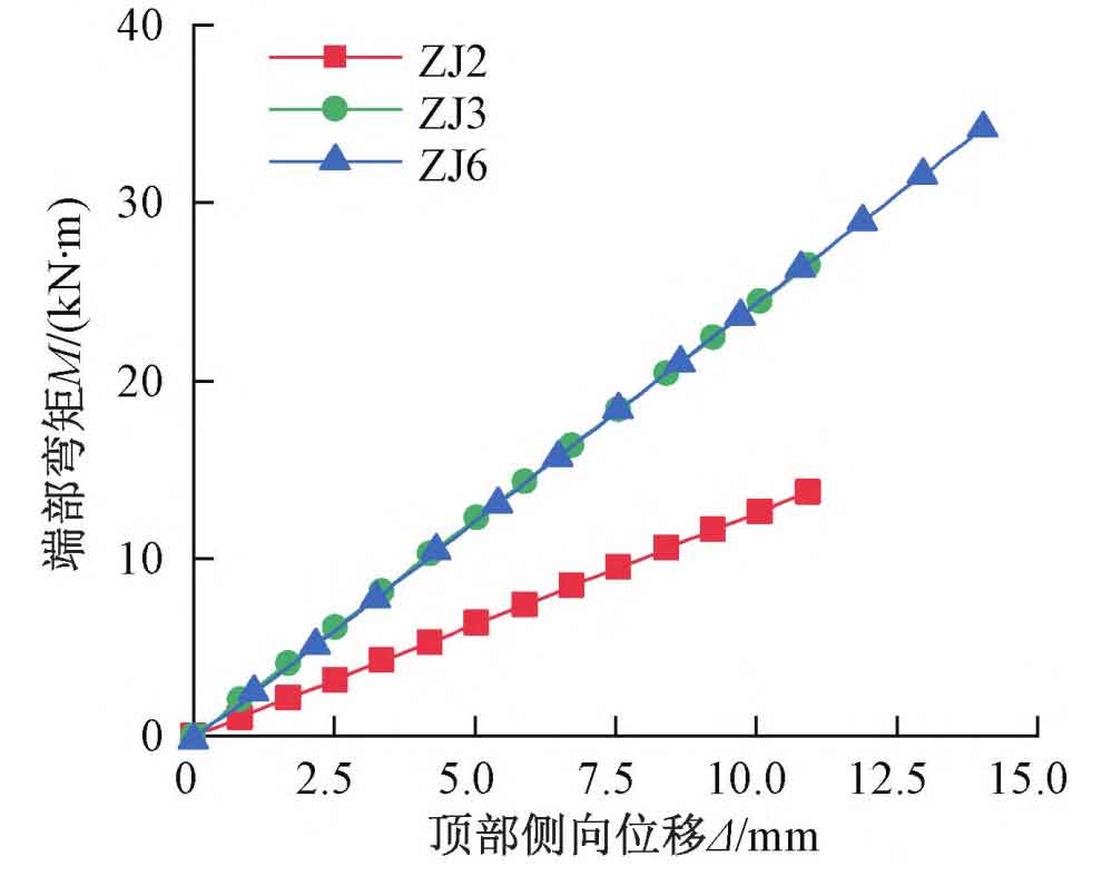
Large scale steel casting manufacturers based on the end bending moment M and top lateral displacementΔ in Figure 1 , The lateral stiffness k of a column in a finite element model can be defined as:
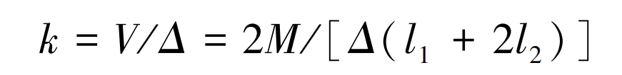
In the formula: V is the shear force acting on the steel column; L1 and l2 are the lengths of seamless steel pipes and cast steel parts, respectively.
1. Simplified model for lateral stiffness of steel columns
Large scale steel casting manufacturers propose two simplified models:
1) The full length range is based on the seamless steel pipe section and fixed joints at both ends (equal section model, Figure 2 (a));
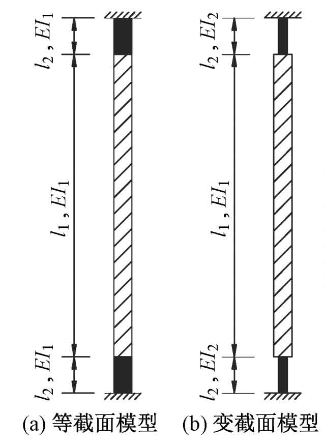
2) Consider the column within the length range of the cast steel node as a member with the same cross-section as the neck of the cast steel component, and the remaining parts are fixed at both ends according to the seamless steel pipe cross-section (variable cross-section model, Figure 2 (b)).
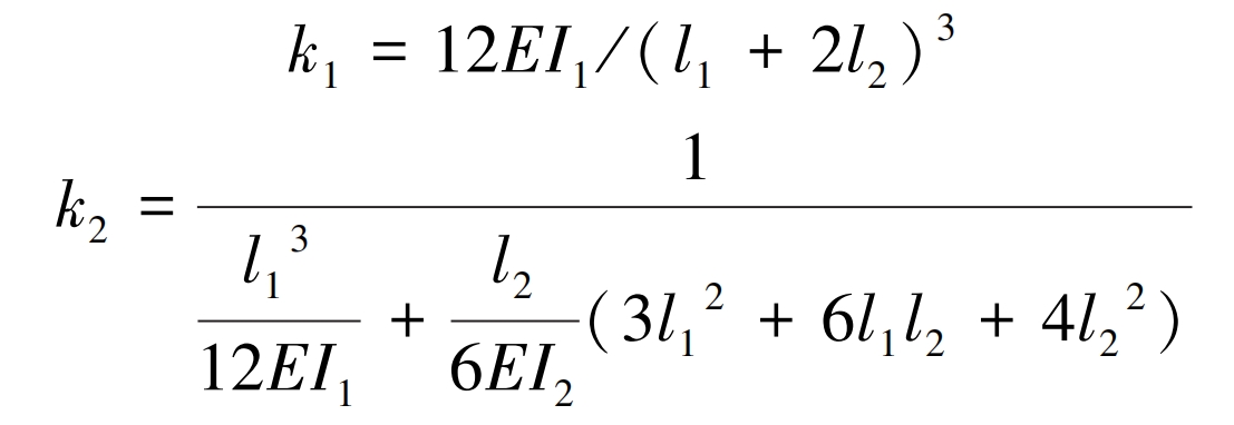
The lateral stiffness k1 of the constant cross-section model and the lateral stiffness k2 of the variable cross-section model can be obtained separately by the formula.
In the formula, EI1 and EI2 represent the bending stiffness of steel pipes and castings, respectively. The calculation results of the lateral stiffness k, k1, and k2 of the steel column are shown in Table 1.
| Column base number | k/(kN/ m) | k1/ (kN/ m) | k / k1 | k2/ (kN/ m) | k / k2 |
| ZJ2 | 227.5 | 451.9 | 0.503 | 222.6 | 1.022 |
| ZJ3 | 455.6 | 713.5 | 0.639 | 460.9 | 0.988 |
| ZJ6 | 343.7 | 821.5 | 0.418 | 353.2 | 0.973 |
As shown in the table:
(1) Steel columns with cast steel column bases have a certain degree of lateral stiffness. When lateral displacement occurs at the top of the column, bending moments will be generated at the column ends. If the column base nodes in the overall model are designed with hinge joints, the steel columns will be inclined towards safety.
(2) Due to the reduction of the end section, the actual lateral stiffness k of the column is 41% of the lateral stiffness k1 of the constant cross-section model 8% to 63% 9%, therefore, in the overall model, if the steel columns are designed with equal cross-sections, the bending moment at the column base under the same lateral displacement is about twice that of the actual situation, which is conservative.
(3) Under different cross-sections, the lateral stiffness k of the column in the finite element model is basically the same as the lateral stiffness k2 of the variable cross-section model, with an error of less than 3%. Designing the steel column according to the variable cross-section model can accurately reflect the lateral stiffness of the steel column.
Due to the varying axial forces and heights of the columns in the overall model, the column base ZJ3 will be used as the analysis model for parameter analysis in the following text to verify the applicability of the simplified model.
2. The influence of axis force on the lateral stiffness of steel columns
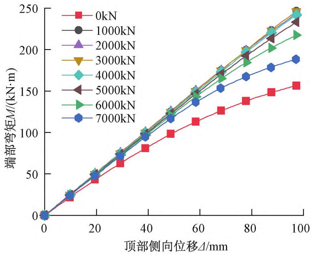
Adjust the axial force at the top of the column in the analysis model, and establish models for axial forces of 0, 1000, 2000, 3000, 4000, 5000, 6000, and 7000kN respectively, while increasing the displacement load to 100mm.
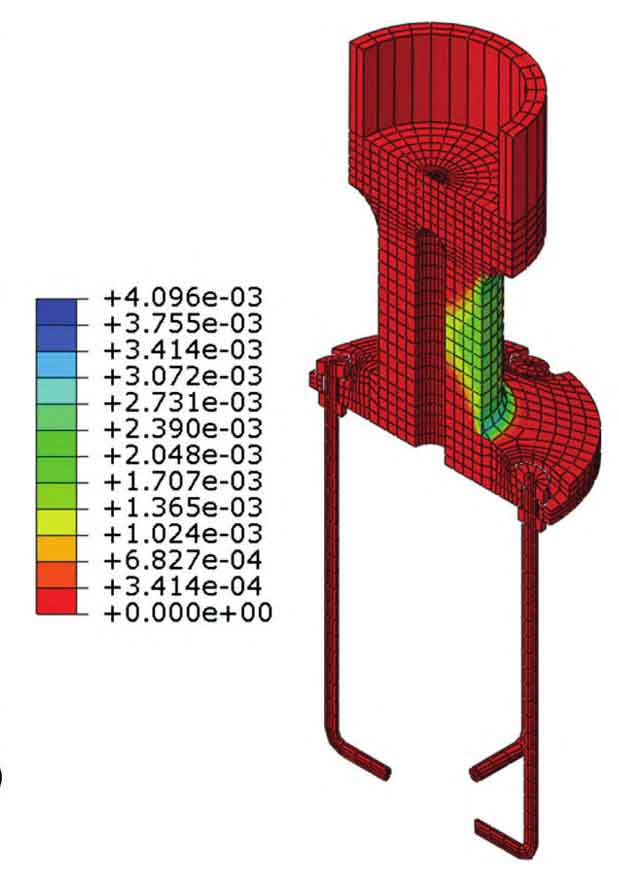
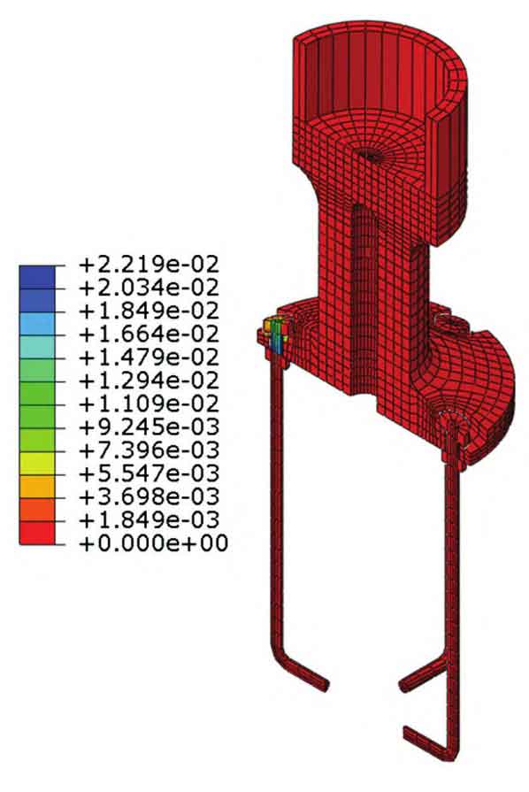
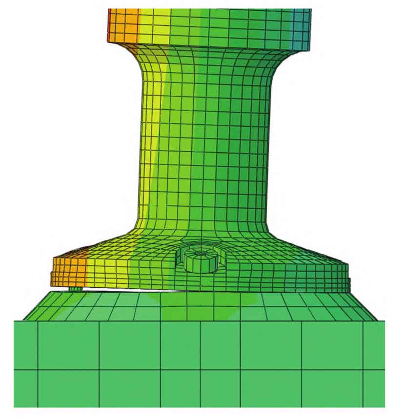
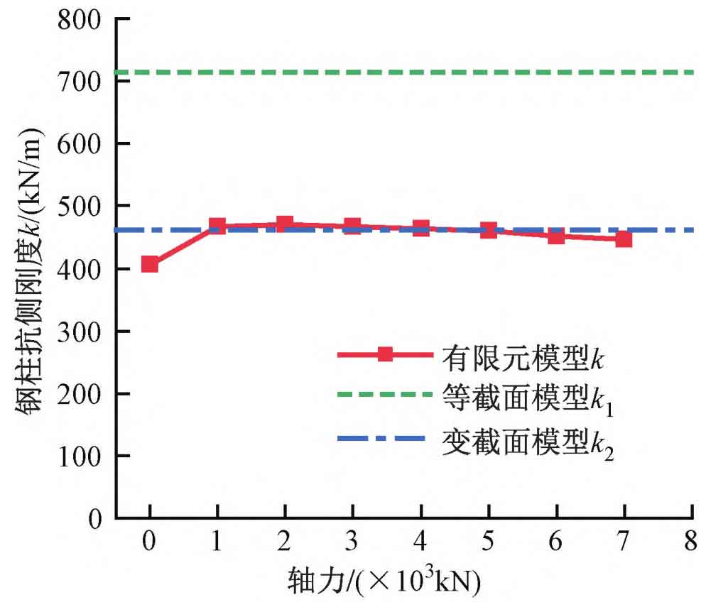
The bending moment M at the end of each analysis model varies with the lateral displacement at the top Δ The variation of M is shown in Figure 3. It can be seen from the figure that when the axial force of the steel column is 1000-4000kN, under the set lateral displacement, M varies with Δ The node maintains elasticity while increasing linearly. As the axial compression ratio increases, when the lateral displacement at the top is large, the lateral stiffness shows significant degradation, and the node area enters plasticity. Figure 4 shows the equivalent plastic strain cloud map of the column base node under an axial force of 7000kN and a lateral displacement of 100mm at the top. It can be seen from the figure that under larger axial forces, the steel casting yields under compression, while the anchor bolts and steel columns remain elastic. Figure 5 shows the equivalent plastic strain of the column base node when the axial force is 0 and the top displacement is 100mm. It can be seen from the figure that plastic deformation is mainly concentrated at the tension side anchor bolt, while cast steel and seamless steel pipes still maintain elasticity. When the axial force is 0, the lateral stiffness of the steel column significantly decreases compared to when there is axial force, and the stiffness degradation is more severe compared to models with high axial compression ratios. As shown in Figure 6, when the axial force is small, the column base plate and foundation detach, and the anchor bolt undergoes tensile deformation. The relationship between the initial lateral stiffness of steel columns and axial force is shown in Figure 7. From the figure, it can be seen that when the axial force is not 0, k is 447-470kN/m, and the error with the lateral stiffness k2 of the variable cross-section model is within 4%. When the axial force is 0, the initial lateral stiffness of the steel column is 406kN/m, with an error of 12% compared to the lateral stiffness k1 of the constant cross-section model.
3. The influence of column height on the lateral stiffness of steel columns
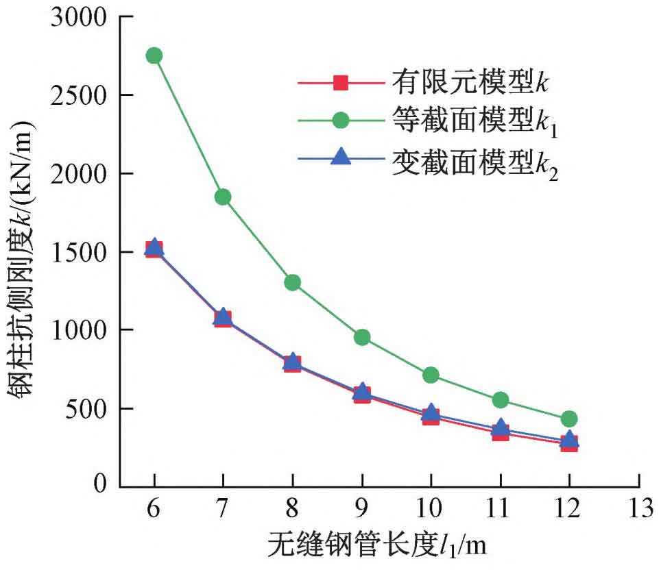
Adjust the length l1 of the seamless steel pipe in the analysis model, take the column top load of 7000kN, and increase the displacement load to 100mm. The relationship between the initial lateral stiffness of steel columns and their height is shown in Figure 8. As shown in the figure, the simplified models with varying cross-sections under different column heights can all match well with the finite element model. The errors of k2 and k increase with the increase of column height, and the maximum error is within 8%.
Based on the above analysis, it can be concluded that designing steel columns as simplified models with variable cross-sections in the overall model can better reflect the connection form of column base nodes. For steel columns with small axial force and tensile deformation of anchor bolts, the steel column with this simplified model has a higher lateral stiffness, and the bending moment of the steel column in the overall model is larger than in reality, resulting in a design bias towards safety. In the construction drawing design, the steel columns in the overall model were modeled and verified using this method. The maximum stress ratio of the steel columns was 0.82. The stress of the cast steel neck section in the adjusted overall model is shown in Table 2. It can be seen from the table that the stress ratio of the steel casting neck meets the design requirements.
| Column base number | Equal cross-section model N/Af | Equal cross-section model M fixed connection/ γWf | Equal section model total stress ratio | Variable cross-section model N/Af | Variable cross-section model M fixed connection/ γWf | Total stress ratio of variable cross-section model |
| ZJ2 | 0.45 | 0.73 | 1.18 | 0.45 | 0.38 | 0.83 |
| ZJ3 | 0.54 | 0.48 | 1.02 | 0.54 | 0.28 | 0.83 |
| ZJ6 | 0.59 | 0.61 | 1.21 | 0.60 | 0.29 | 0.89 |
(1) Under the design load, each cast steel column base node maintains elasticity and has a certain safety reserve.
(2) The axial force of the steel column is not transmitted solely through shear force to the neck of the cast steel, but a portion is directly transmitted from the wall of the steel column to the neck of the cast steel through pressure. The bending moment at the root of the top tray is significantly smaller than that calculated by the cantilever plate.
(3) The compressive stress on the bottom plate of the column foot is not uniformly distributed, and using traditional methods for design is too conservative. When the base plate of the column adopts the preliminary design size, there is a significant surplus in bearing capacity; There was no significant damage to the concrete.
(4) The steel column with variable cross-section cast steel column base has a lateral stiffness between the ideal hinge joint at both ends and the ideal fixed joint at both ends. Designing steel columns with equal cross-sections and fixed connections at both ends will overestimate the bending moment acting on the steel columns and column bases.
(5) By analyzing the lateral stiffness of models with different cross-sections, axial forces, and column heights, designing steel columns as simplified models with variable cross-sections and fixed connections at both ends can better reflect the connection form of column base nodes.