
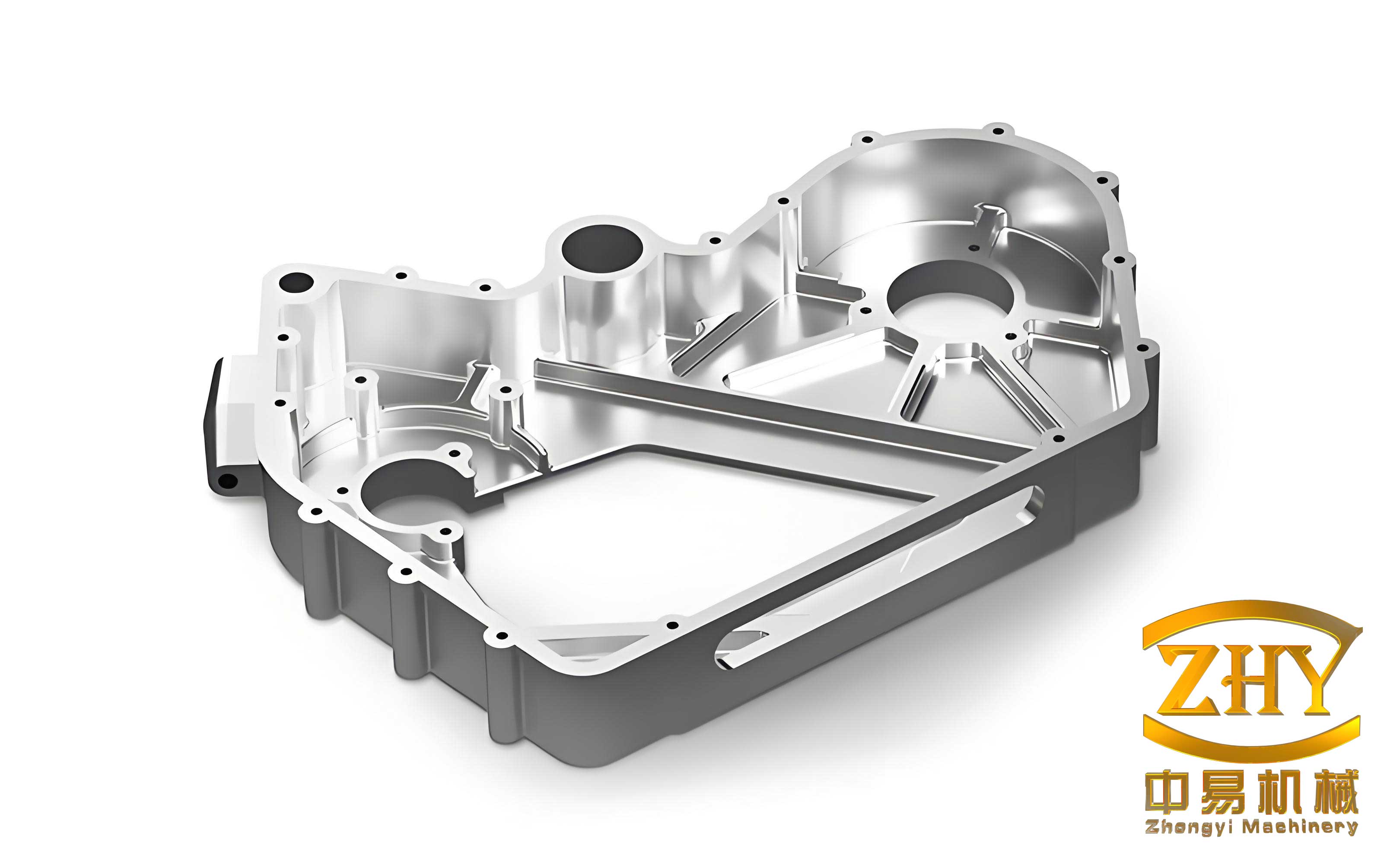
In my extensive experience within the foundry industry, specializing in the production of water faucet bodies—critical components often referred to as shell castings due to their complex, hollow structure—I have consistently encountered and addressed the pervasive issue of leakage during pressure testing. These shell castings, typically made from leaded brass like ZCuZn40Pb2, are characterized by intricate geometries, thin average wall sections around 3 mm, and stringent quality requirements that demand absolute freedom from defects such as cracks, porosity, shrinkage cavities, and micro-shrinkage. The manufacturing process involves metal mold casting, which offers advantages like dense microstructure, high productivity, and good yield, yet it inherently poses challenges like poor gas venting and limited mold yield that often lead to leakage, particularly in critical zones like the hot-cold water partition wall. This article delves into a comprehensive, first-person analysis of the root causes behind this leakage in shell castings and presents a detailed suite of proven countermeasures, emphasizing the unique behaviors of shell-type solidification. To aid visualization of typical defect locations in such components, consider the following illustration:
The phenomenon of leakage in these shell castings is not merely a surface imperfection but a critical failure mode that directly compromises product functionality and safety. Through systematic investigation and process refinement, I have identified that leakage primarily stems from a confluence of factors: inherent material deficiencies, the formation of micro-shrinkage porosity driven by solidification characteristics, and suboptimal casting工艺 parameters. The very nature of shell castings, with their enclosed cores and rapid external cooling, creates a unique solidification dynamic that must be meticulously managed.
Fundamental Solidification Behavior in Shell Castings
The leakage problem is fundamentally rooted in the solidification physics of the leaded brass alloy used for these shell castings. This alloy has a narrow freezing range, which typically promotes a skin-forming or “shell” mode of solidification. However, the geometry of the faucet body—especially features like internal ribs, bosses (often termed “搭子” in the context), and the partition wall—creates localized thermal masses that alter this ideal behavior. The external surfaces, in contact with the metal mold, cool rapidly, forming a sound, dense shell. In contrast, internal regions surrounded by sand cores cool more slowly, leading to what can be described as an endothermic or quasi-pasty solidification mode in those specific hot spots. This differential cooling establishes thermal gradients and feeding paths that are crucial to understand.
The solidification time for a section can be approximated using Chvorinov’s rule:
$$ t_s = B \left( \frac{V}{A} \right)^n $$
where \( t_s \) is the solidification time, \( V \) is the volume of the casting section, \( A \) is its surface area, \( B \) is a mold constant, and \( n \) is an exponent typically around 2 for many casting processes. For shell castings with complex internal features, the modulus \( (V/A) \) for hot spots like bosses is high, leading to prolonged solidification and increased susceptibility to shrinkage defects. The pressure tightness of the final shell castings is directly threatened by the formation of intergranular and interdendritic micro-porosity in these late-solidifying zones.
Furthermore, the ability of the molten metal to feed these shrinking regions is governed by fluid flow and pressure drop. Darcy’s law for flow through a mushy zone can be conceptualized:
$$ v = -\frac{K}{\mu} \nabla P $$
where \( v \) is the filtration velocity, \( K \) is the permeability of the dendritic network (which decreases drastically as solid fraction increases), \( \mu \) is the dynamic viscosity, and \( \nabla P \) is the pressure gradient. In the isolated hot spots of shell castings, the permeability becomes critically low near the end of solidification, starving the region of feed metal and resulting in micro-shrinkage. This micro-shrinkage, often invisible to the naked eye, forms interconnected pathways that cause leakage under hydrostatic pressure.
Comprehensive Analysis of Leakage Causative Factors
My investigation categorizes the primary causes of leakage in these brass shell castings into three interconnected domains: material quality, solidification-induced defects, and process execution.
1. Material Quality and Metallurgical Factors
The foundation of sound shell castings lies in the purity and consistency of the alloy. The use of low-grade copper and zinc ingots, excessive reliance on recycled returns (often exceeding 25-30%), and inadequate熔炼 control introduce a host of detrimental elements and gases. Key impurities like iron, lead segregation, and dissolved hydrogen severely degrade casting performance. Hydrogen, in particular, has high solubility in molten copper alloys that drops precipitously upon solidification, leading to gas porosity that can synergize with shrinkage to create leak paths.
The thermodynamic potential for gas dissolution is given by Sieverts’ law:
$$ C_{H} = K_{H} \sqrt{P_{H_2}} $$
where \( C_{H} \) is the concentration of dissolved hydrogen, \( K_{H} \) is the equilibrium constant (temperature-dependent), and \( P_{H_2} \) is the partial pressure of hydrogen in the atmosphere. During melting without proper flux cover, \( P_{H_2} \) from furnace atmosphere or moisture increases, raising \( C_{H} \). Upon cooling, supersaturation leads to bubble nucleation, often at the already vulnerable interdendritic regions in shell castings.
The table below summarizes the detrimental effects of key impurities and gases on the integrity of shell castings:
| Element/Contaminant | Primary Source | Effect on Shell Castings | Link to Leakage |
|---|---|---|---|
| Hydrogen (H₂) | Wet charge materials, humid atmosphere, incomplete flux cover | Forms pinhole and micro-porosity upon solidification | Creates direct leak paths or expands shrinkage cavities |
| Oxygen (O₂) | Oxidation during melting, poor deoxidation practice | Forms oxide inclusions (Cu₂O, ZnO) and dross | Inclusions act as stress raisers and block feeding channels |
| Excess Iron (Fe) | Low-grade scrap, steel tool contamination | Forms hard, brittle intermetallic phases (e.g., Fe-rich compounds) | Promotes hot tearing and cracks, providing leakage conduits |
| Uncontrolled Lead (Pb) | Segregation in returns, inaccurate charging | Leads to inverse segregation and intergranular weakness | Weakens grain boundaries, facilitating crack propagation |
| High Return Ratio | Economic practice, but >25% is risky | Accumulates tramp elements, increases gas content, alters effective composition | Degrades overall metallurgical quality, increasing defect propensity |
2. Micro-shrinkage: The Predominant Defect in Shell Castings
Micro-shrinkage, or shrinkage porosity, is the most insidious cause of leakage in pressure-tight shell castings. It results from inadequate compensation for the volumetric shrinkage of the alloy as it transitions from liquid to solid. In shell castings, this is exacerbated by the geometry. Features like the冷热水隔墙 (partition wall) and mounting bosses are essentially isolated thermal masses surrounded by the insulating sand core. They solidify last, and the feeding path from the main runner or riser is often long and tortuous.
The tendency for shrinkage porosity formation can be evaluated using criteria like the Niyama criterion, originally developed for steel but conceptually applicable. It relates the local thermal conditions to pore formation:
$$ G / \sqrt{\dot{T}} $$
where \( G \) is the temperature gradient and \( \dot{T} \) is the cooling rate at the solidus front. A lower value of this ratio indicates a higher risk of micro-porosity. In the hot spots of shell castings, \( G \) is low (due to slow, directional heat extraction) and \( \dot{T} \) is also relatively low, resulting in a critically low ratio. This condition favors the formation of a mushy zone that is extensive and impermeable, preventing adequate feeding.
The volumetric shrinkage requiring feeding can be estimated as:
$$ \Delta V = V_0 \cdot (\beta_l \cdot \Delta T_l + \beta_s \cdot \Delta T_s + \epsilon) $$
where:
- \( V_0 \): Initial liquid volume
- \( \beta_l \): Liquid thermal contraction coefficient
- \( \Delta T_l \): Temperature drop in the liquid state before solidification
- \( \beta_s \): Solid thermal contraction coefficient
- \( \Delta T_s \): Temperature drop in the solid state after solidification
- \( \epsilon \): Volumetric shrinkage due to the liquid-to-solid phase change (typically ~4-6% for brasses)
For ZCuZn40Pb2, the phase change shrinkage \( \epsilon \) is significant. If the feeding system—designed for the overall shell casting—cannot deliver liquid to these specific hot spots to compensate for this \( \Delta V \), micro-shrinkage forms. This defect network is highly effective in causing leakage in shell castings subjected to water pressure tests.
3. Process-Related Deficiencies
Even with good material and design, leakage in shell castings can arise from suboptimal process control during mold preparation, pouring, and solidification.
Gating and Feeding System Design: An ill-designed gating system can cause turbulent filling, promoting air entrapment and oxide formation. More critically for shell castings, if the feeder (riser) does not create a directional solidification pattern towards itself from the hot spots, shrinkage defects are inevitable. The feeding distance is finite. For a given modulus, the maximum effective feeding distance \( L_f \) can be approximated by:
$$ L_f \propto \frac{\Delta P \cdot K}{\mu \cdot f_s} $$
where \( \Delta P \) is the feeding pressure (metallostatic head + atmospheric pressure), \( K \) is permeability, \( \mu \) is viscosity, and \( f_s \) is the solid fraction. In shell castings with internal cores, \( \Delta P \) on an isolated boss can be minimal, drastically reducing \( L_f \).
Core-Related Issues: The resin-bonded sand cores used to form the internal cavities of shell castings are a double-edged sword. If not adequately cured or if their composition has poor collapsibility, they introduce problems. An under-cured core releases large volumes of gas during pouring, leading to gas porosity. A core with excessive strength and poor collapsibility hinders the natural contraction of the solidifying shell casting, inducing tensile stresses that can result in hot tears or cracks—direct leakage paths. The gas generation rate from a core can be modeled as a function of temperature:
$$ \dot{Q}_{gas} = A_c \cdot \rho_c \cdot r(T) $$
where \( \dot{Q}_{gas} \) is the volumetric gas generation rate, \( A_c \) is the core surface area, \( \rho_c \) is the core density, and \( r(T) \) is a temperature-dependent reaction rate for binder decomposition. This gas must escape through the core vents and the mold; otherwise, it gets trapped in the metal.
Pouring Parameters: Pouring temperature and speed are critical. A high pouring temperature, while improving fluidity, increases total heat content, enlarges the mushy zone in hot spots, and aggravates shrinkage porosity in shell castings. It also promotes more metal-mold reaction and gas pickup. A low pouring temperature may lead to mistruns but, if optimized, reduces shrinkage. Pouring speed affects mold filling turbulence. The Reynolds number \( Re = \frac{\rho v D}{\mu} \) should be kept below a critical value (often ~2000 for laminar flow in gating systems) to minimize turbulence.
The following table outlines key process parameters, their typical problematic ranges, and their direct impact on leakage in shell castings:
| Process Parameter | Problematic Range / Condition | Mechanism of Defect Formation | Resultant Defect Leading to Leakage |
|---|---|---|---|
| Pouring Temperature | > 1010°C for ZCuZn40Pb2 | Increased total shrinkage, prolonged solidification time of hot spots, higher gas solubility | Enlarged micro-shrinkage zones, gas porosity |
| Pouring Time / Speed | Too fast, < 3 seconds for a typical shell casting | Turbulent filling, air entrapment, erosion of mold coatings | Cold shuts, dross entrainment, gas holes |
| Metal Mold Temperature | Too low (< 150°C) or uneven | Excessive thermal shock, premature freezing of gates, high thermal gradients | Hot tears, mistruns, misruns, stress cracks |
| Sand Core Condition | Insufficient curing (moisture > 0.8%), high binder content, poor venting | High gas evolution during pour, low collapsibility | Core gas blows, shrinkage restraint causing cracks |
| Mold Venting | Inadequate vent area or placement | Trapped air and core gases cannot escape | Surface and subsurface blowholes, porosity |
| Feeder (Riser) Design | Insufficient modulus, poor thermal connection to hot spot | Inadequate feed metal volume and pressure during solidification | Shrinkage cavity or dispersed micro-shrinkage |
Integrated Countermeasure Strategy for Leakage Prevention
Based on the root cause analysis, a multi-pronged approach is essential to manufacture leak-proof shell castings. The strategy must address material, design, and process simultaneously.
1. Advanced Mold and Gating System Design for Shell Castings
Modifying the mold design is the first line of defense. For the shell castings in question, specific interventions include:
- Enhanced Venting: Incorporating strategic vent channels is non-negotiable. In my practice, machining 2 mm deep triangular grooves on the core prints and adding 2 mm thick flat vents at the mold parting line dramatically improved gas evacuation. The vent area should be at least 1-3% of the projected cavity area for such shell castings.
- Directed Feeding & Chilling: Given that the boss (“搭子”) is a recurrent hot spot, the gating system must be designed to promote directional solidification towards a feeder or a chill. This involves increasing the cross-sectional area (modulus) of the ingate connecting to the boss region. Effectively, we aim to make the ingate solidify after the boss, acting as a feeder. The modulus \( M \) of a section is \( V/A \). For effective feeding, \( M_{feeder} > M_{casting} > M_{gate} \) is the ideal sequence for directional solidification away from the casting. However, for an isolated hot spot in a shell casting, we sometimes invert this locally: \( M_{gate\_to\_boss} > M_{boss} \) to ensure the gate feeds the boss.
- Application of Exothermic or Insulating Sleeves: On risers attached to shell castings, using exothermic sleeves maintains liquid feed metal for longer, extending feeding range.
2. Metallurgical Refinement and Alloy Treatment
Superior melt quality is paramount for producing integral shell castings.
- Raw Material Control: Insist on high-purity cathode copper and special high-grade zinc. Limit the use of internal returns (recycled castings, gates) to below 25% of the total charge. This minimizes the accumulation of harmful trace elements and gases.
- Melting Practice: Employ a protective covering flux throughout the melting cycle. A proven mixture is 70% borax (Na₂B₄O₇) and 30% crushed glass. This forms a viscous, continuous layer that shields the melt from atmospheric oxygen and hydrogen. All tools, crucibles, and charge materials must be preheated to above 150°C to eliminate moisture.
- Degassing and Refining: Actively degas the melt using dry nitrogen or argon purging. Phosphorus copper (P-Cu) can be used as a deoxidizer cautiously to reduce oxide content. The reaction is: $$ 5Cu_2O + 2P \rightarrow 10Cu + P_2O_5_{(g)} $$ The P₂O₅ gas escapes, reducing dross.
- Grain Refinement and Modification: The addition of rare earth (RE) elements in small quantities (0.03–0.05 wt%) has a profound effect. RE elements like Cerium and Lanthanum act as potent grain refiners and sulfide/oxide modifiers. They enhance the fluidity of the alloy in the mushy state, improve feeding, and reduce the size and connectivity of micro-shrinkage pores in shell castings. The mechanism involves forming high-melting-point compounds that serve as heterogeneous nucleation sites, refining the as-cast grain structure according to the free growth model:
$$ \Delta T_{fg} = \frac{4 \sigma_{sl}}{\Delta S_v \cdot d_{pot}} $$
where \( \Delta T_{fg} \) is the undercooling needed for free growth on a potent substrate of diameter \( d_{pot} \), \( \sigma_{sl} \) is the solid-liquid interfacial energy, and \( \Delta S_v \) is the entropy of fusion per unit volume. RE additions increase the number of potent substrates, reducing \( \Delta T_{fg} \) and leading to a finer grain size, which improves mechanical properties and pressure tightness of shell castings.
A recommended charge makeup and treatment practice is summarized below:
| Stage | Action | Specification / Target | Benefit for Shell Castings |
|---|---|---|---|
| Charge Preparation | Select raw materials | >99.9% Cu cathode, SHG Zinc, Returns < 25% | Minimizes impurity ingress, ensures consistent composition |
| Melting | Apply cover flux | 70% Borax + 30% Glass, full surface cover | Prevents oxidation and hydrogen pickup |
| Superheating | Hold at temperature | 1020-1050°C for 10-15 min under flux | Promotes homogenization and dross separation |
| Treatment | Degas & Additive | Argon purge for 3-5 min, then add 0.04% RE master alloy | Removes dissolved H₂, refines grain structure, modifies inclusions |
| Temperature Control | Adjust before pouring | Cool to and maintain at (990 ± 10)°C | Optimal fluidity with reduced shrinkage tendency |
3. Precision Process Control for Shell Castings Production
Execution at the molding and pouring stations determines the success of the design and metallurgy.
- Optimal Pouring Parameters: A pouring temperature of (990 ± 10)°C has been empirically established as the sweet spot for ZCuZn40Pb2 shell castings. It provides sufficient fluidity to fill thin sections while minimizing total heat. Pouring should be smooth and non-turbulent. For the typical shell casting weighing 500-2000g, a controlled pour time of approximately 4 seconds is achieved by adjusting the tilt speed of the pouring furnace. This allows for a more laminar fill, letting gases escape ahead of the metal front.
- Core Quality Management: Shell cores (or hot-box cores) must be fully cured. A properly cured phenolic-urethane or similar resin-bonded core should have a uniform coffee-brown color with a slight gloss; a scratch test should reveal a white mark without sand grain dislodgement. Core designs must include internal venting channels (hollow core prints) to provide an escape route for gases. The choice of sand and binder is critical: a high-quality coated sand with good collapsibility after casting is essential to avoid hot tearing in the confined sections of shell castings.
- Localized Cooling Control – Use of Chills and Coatings: For the specific hot spot like the进水腔 boss, a targeted approach is highly effective. Applying a coating containing a strong chilling agent like Tellurium (Te) on the corresponding sand core surface can dramatically alter the local solidification. A slurry of Te powder in alcohol (forming a fast-drying coating about 0.2–0.4 mm thick) is painted on the core. Tellurium, having a high thermal conductivity and acting as an inoculant, promotes rapid solidification at that interface, effectively turning the hot spot into a chilled zone. This reverses the thermal gradient, encouraging directional solidification towards the main casting body or feeder, thus eliminating the isolated mushy zone. The effectiveness can be related to the increase in the local heat transfer coefficient \( h \) at the metal-core interface:
$$ q = h \cdot (T_{metal} – T_{core}) $$
where \( q \) is the heat flux. The Te coating increases \( h \), thereby increasing \( q \) and the local cooling rate \( \dot{T} \), which as per the Niyama criterion, reduces shrinkage risk. - Mold Temperature Management: Preheating the metal mold to a consistent temperature (e.g., 200-250°C) and maintaining it with a thermal management system ensures uniform cooling and reduces thermal shock, minimizing stress-related cracks in the shell castings.
To encapsulate the optimized process window, the following set of equations and parameters defines the recommended operational envelope for producing leak-tight shell castings:
Key Process Control Equations & Limits:
1. Pouring Temperature Constraint:
$$ T_{pour} = 990 \pm 10 \, ^\circ\text{C} $$
2. Pouring Time for Laminar Flow (Empirical):
$$ t_{pour} \approx 4 \times \left( \frac{W}{1500} \right)^{0.5} \, \text{seconds} \quad \text{for casting weight } W \text{ in grams} $$
3. Core Gas Evolution Limit (Qualitative): Core moisture content must satisfy:
$$ \text{Moisture}_{core} < 0.8\% \quad \text{and} \quad \text{Curing Degree} > 95\% $$
4. Mold Venting Sufficiency Criterion:
$$ A_{vents} \geq 0.02 \times A_{projected} $$
where \( A_{vents} \) is the total vent cross-sectional area and \( A_{projected} \) is the projected area of the cavity.
5. Feeding Requirement for a Hot Spot:
$$ V_{riser} \geq \frac{ \epsilon \cdot V_{hotspot} }{ \eta } $$
where \( \epsilon \) is the solidification shrinkage fraction (~0.05), \( V_{hotspot} \) is the volume of the isolated thermal mass, and \( \eta \) is the feeding efficiency (typically 0.1-0.3 for blind risers in shell castings).
Production Validation and Economic Impact
Implementing this integrated approach has yielded transformative results in the production of shell castings for faucet bodies. The leakage failure rate during hydrostatic pressure testing (typically at 1.6 MPa for 30 seconds) plummeted from an initial, unacceptable level often exceeding 50% to a consistently low rate below 10%. In many production batches for shell castings like the CL316 model, the scrap rate due to leakage and other associated defects has been reduced to under 5%, effectively increasing the yield from around 50% to over 90%.
The microstructural evidence corroborates the improvement. Metallographic analysis of sections from the critical partition wall and boss areas revealed a significant reduction in the size, number, and interconnectivity of micro-shrinkage pores. The grain structure was noticeably finer and more equiaxed due to the rare earth treatment, enhancing the overall density and pressure integrity of the shell castings.
The economic benefits are substantial. The reduction in scrap directly lowers material and energy costs per good casting. The increased consistency and reliability of the shell castings streamline subsequent machining and polishing operations, reducing rework and inventory of doubtful parts. Furthermore, the enhanced reputation for delivering high-quality, leak-proof shell castings strengthens market competitiveness.
In conclusion, the leakage in metal mold cast brass shell castings is a solvable engineering challenge. It demands a holistic understanding of the interplay between alloy solidification behavior (the shell casting’s inherent characteristic), material purity, and precise process control. By systematically addressing the metallurgical quality through refined melting and grain modification, redesigning the mold for effective venting and directional feeding, and implementing stringent control over pouring parameters and core quality, foundries can achieve exceptional levels of pressure tightness in these complex shell castings. The success hinges on treating the shell casting not just as a shaped metal object but as a solidification system where thermal management and feeding mechanics dictate the final quality. Continuous monitoring and statistical process control of the key parameters outlined herein will ensure the sustained production of reliable, leak-free shell castings for demanding applications.