
In the automotive industry, the camshaft is a critical component of engine systems, directly influencing combustion efficiency, fuel economy, and overall engine performance. The adoption of ductile iron for camshaft manufacturing has gained traction due to its favorable mechanical properties and cost-effectiveness. However, achieving consistent high-quality ductile iron camshafts, particularly in terms of本体性能 (本体性能 refers to the inherent properties of the cast part without additional processing), remains challenging due to defects like shrinkage porosity and micro-shrinkage that arise during solidification. This study focuses on utilizing the sand coated iron mold casting technique to produce synthetic ductile iron camshafts with the grade QT600-3, aiming to analyze their本体性能 and establish correlations between microstructure and mechanical properties. By employing scrap steel and returns as primary raw materials, this approach not only reduces alloy usage and costs but also promotes resource efficiency. The process involves carburizing to adjust carbon content, followed by rigorous球化 (nodularization) and孕育 (inoculation) treatments. Throughout this article, I will elaborate on the experimental methodology, results, and insights gained, emphasizing the role of sand coated iron mold casting in enhancing performance.
The sand coated iron mold casting process combines the advantages of metal mold and shell molding, offering high cooling rates and significant mold rigidity. This is particularly beneficial for ductile iron, which undergoes a “mushy” solidification, leading to graphite expansion that can cause dimensional instability and internal defects. The rigidity of the sand coated iron mold constrains this expansion, facilitating better feeding and reducing shrinkage defects. Moreover, the rapid cooling promotes the formation of pearlite, essential for achieving high strength in grades like QT600-3. In this study, I designed the experiments to leverage these characteristics, ensuring that the本体性能 meet the stringent requirements for automotive applications. The following sections detail the材料 selection, processing parameters, and analytical techniques used.
To achieve the desired QT600-3 grade, the chemical composition was meticulously designed based on standard guidelines and prior research. The composition must balance graphite formation, matrix structure, and mechanical properties. For sand coated iron mold casting, the rapid cooling necessitates adjustments to promote pearlite while maintaining adequate ductility. The target chemical ranges are summarized in Table 1.
| Element | Content Range (wt.%) | Role in Ductile Iron |
|---|---|---|
| C | 3.8 – 3.9 | Promotes graphite nodule formation, reduces shrinkage, enhances fluidity |
| Si | 2.6 – 2.7 | Graphitizer, increases ferrite content, balances pearlite formation |
| Mn | ≤ 0.20 | Stabilizes pearlite but can segregate; kept low to avoid brittleness |
| Cu | 0.35 – 0.45 | Alloying element that strengthens matrix, promotes pearlite, reduces carbides |
| P | ≤ 0.06 | Impurity that can form phosphides; minimized for toughness |
| S | ≤ 0.05 | Interferes with球化; kept low for effective nodularization |
Carbon is crucial for ensuring a high graphite nodule count and roundness, which mitigate the cutting effect on the matrix. The carbon equivalent (CE) is a key parameter, calculated as: $$CE = C + \frac{Si}{3} + \frac{P}{3}$$ For our composition, CE ranges from approximately 4.5 to 4.6, indicating a hypereutectic tendency that favors graphite precipitation. Silicon aids in graphitization and ferrite formation; however, in sand coated iron mold casting, its content is controlled to counterbalance the rapid cooling that promotes pearlite. Manganese is limited to below 0.20% to prevent segregation and carbide formation at grain boundaries. Copper is added as an alloying element to enhance strength and pearlite content without excessive hardness. Phosphorus and sulfur are restricted to low levels to ensure good toughness and effective球化.
Two charge material schemes were compared: synthetic ductile iron using scrap steel (65%) and returns, versus non-synthetic ductile iron using Q10 pig iron (65%) and returns. The synthetic route involves carburizing with graphite-based carburizers to achieve the target carbon content, while the non-synthetic route relies on pig iron’s inherent carbon. This comparison aims to evaluate the impact of raw material purity on本体性能. The sand coated iron mold casting process was applied uniformly to both schemes, with molds prepared using a resin-coated sand layer over an iron mold to achieve the desired cooling characteristics.
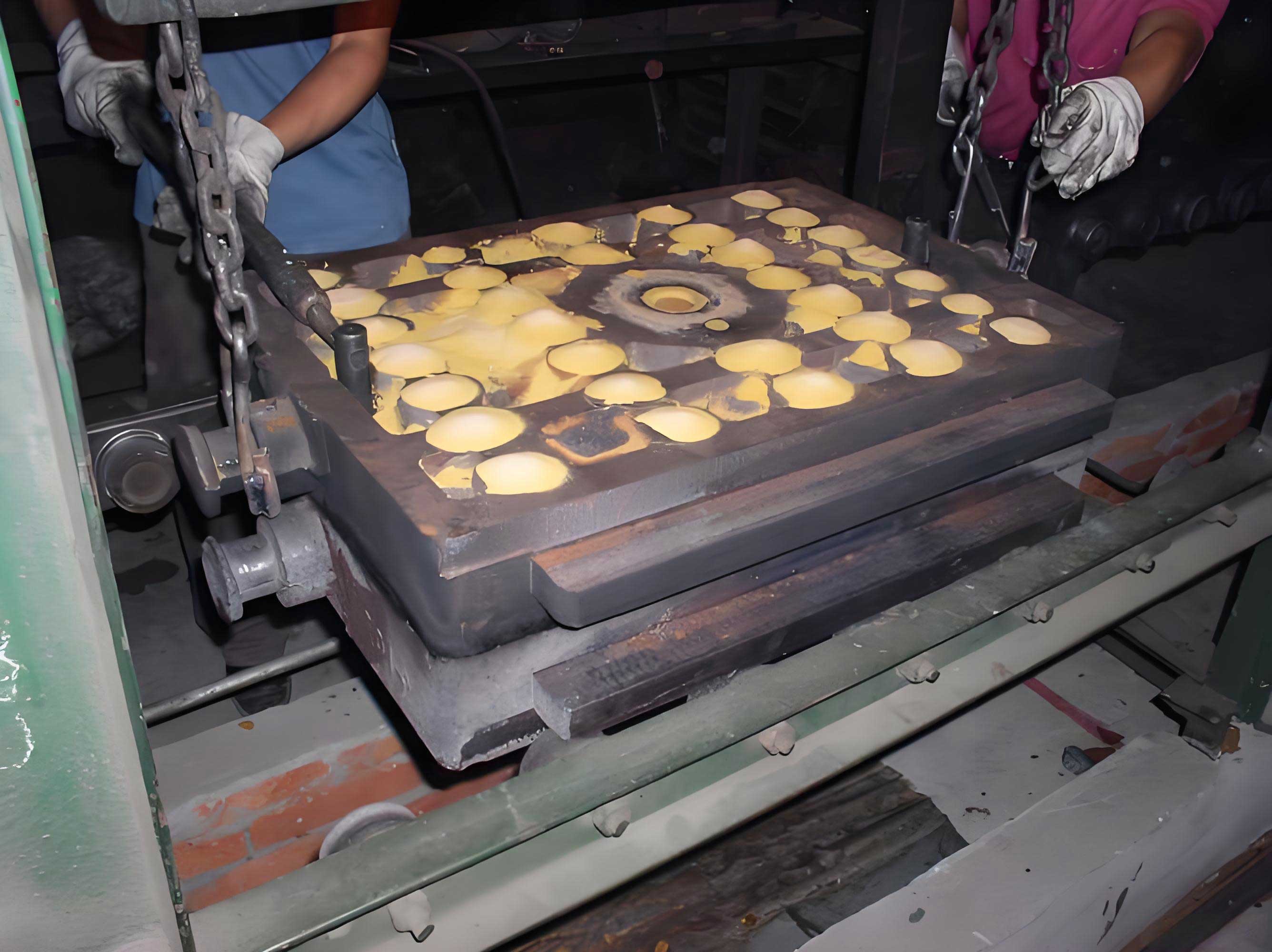
Melting was conducted in a medium-frequency induction furnace. For synthetic ductile iron, scrap steel and returns were charged, followed by carburizer addition to adjust carbon. The melt was superheated to 1520°C to ensure dissolution and homogeneity.球化 treatment was performed using the conventional sandwich method, with rare-earth magnesium ferrosilicon球化剂 added at 1.30–1.45% of the melt weight.孕育 treatment involved three stages: pre-inoculation in the ladle (20% of inoculant), stream inoculation during pouring (60%), and post-inoculation in the transfer ladle (20%). The inoculant was Si-Ca-Ba alloy, added at 1.10–1.30%. This multi-stage孕育 enhances graphite nucleation, leading to finer and more uniform nodules. After treatment, the molten iron was poured into the sand coated iron mold cavities designed for camshafts, with a pouring temperature of 1380–1400°C. The molds were allowed to cool naturally before shakeout.
Specimens for mechanical testing and microstructural analysis were extracted from the camshaft本体, specifically from regions corresponding to high stress areas, as shown in the sampling diagram. Tensile specimens were machined according to GB/T 1348-2009 standards, with a gauge length of 50 mm and diameter of 10 mm. Testing was conducted on a universal testing machine at room temperature, with strain rates per ASTM E8 guidelines. Hardness was measured using a Brinell hardness tester. Microstructural examination involved preparing polished and etched samples (4% nital etch) for optical microscopy and image analysis. Graphite nodule count, size distribution,球化率 (nodularity), and matrix constituents (pearlite and ferrite percentages) were evaluated per GB/T 9441-2009. Additionally, scanning electron microscopy (SEM) was used for detailed analysis of matrix morphology.
The mechanical properties of the synthetic and non-synthetic ductile iron camshafts are summarized in Table 2. Each data point represents the average of three tests from different camshafts produced under identical conditions.
| Sample Type | Tensile Strength (MPa) | Elongation (%) | Hardness (HB) | Pearlite Content (%) | Ferrite Content (%) | Nodularity Grade |
|---|---|---|---|---|---|---|
| Synthetic Ductile Iron | 714 ± 15 | 3.30 ± 0.20 | 240 ± 10 | 75 ± 5 | 25 ± 5 | 2-1 |
| Non-Synthetic Ductile Iron | 624 ± 12 | 1.42 ± 0.15 | 225 ± 10 | 75 ± 5 | 25 ± 5 | 3-2 |
The results clearly indicate that synthetic ductile iron produced via sand coated iron mold casting exhibits superior本体性能. The tensile strength exceeds 700 MPa, and elongation is over 3%, meeting the QT600-3 requirements (≥600 MPa tensile strength, ≥3% elongation). In contrast, non-synthetic ductile iron shows lower tensile strength (around 620 MPa) and significantly reduced elongation (1.42%), failing to achieve the grade specifications despite similar pearlite and ferrite contents. This disparity highlights the importance of raw material selection and the effectiveness of the sand coated iron mold casting process in enhancing properties.
To understand these mechanical property differences, microstructural analysis was conducted. The graphite morphology in synthetic ductile iron revealed a high nodule count, with nodules that are fine, spherical, and uniformly distributed. The nodularity grade is 2-1 per GB/T 9441-2009, indicating excellent球化 with over 95% nodularity. Graphite nodule diameters ranged from 15 to 25 μm, corresponding to size grades 6-7. The increased nodule count is attributed to the use of scrap steel and carburizer, which introduce numerous heterogeneous nucleation sites. The number of nodules per unit area (NA) can be quantified as: $$N_A = \frac{4N}{\pi d^2}$$ where N is the count in a given area and d is the average diameter. For synthetic ductile iron, NA was measured as 250–300 nodules/mm², compared to 150–200 nodules/mm² for non-synthetic iron. This finer graphite structure reduces stress concentration and matrix cracking, thereby improving strength and ductility.
The matrix structure consisted of a mixture of pearlite and ferrite, with no free cementite observed. In both synthetic and non-synthetic irons, the pearlite content was controlled at 65–80% and ferrite at 20–35%, as required for QT600-3. However, the morphology differed significantly. In synthetic ductile iron, the pearlite exhibited a fine lamellar structure, with interlamellar spacing (λ) measured at 0.2–0.3 μm using image analysis. The ferrite appeared as “bull’s-eye” formations surrounding graphite nodules, indicating diffusion-controlled growth during eutectoid transformation. The relationship between tensile strength (σb) and microstructure can be expressed empirically as: $$\sigma_b = \sigma_0 + k_P \cdot P + k_F \cdot F + k_G \cdot \frac{1}{\sqrt{d}}$$ where σ0 is a base strength, kP and kF are coefficients for pearlite and ferrite contributions, P and F are volume fractions, kG is a graphite-related factor, and d is graphite nodule diameter. For synthetic ductile iron, the fine pearlite and small graphite nodules contribute to higher σb values.
The enhanced performance of synthetic ductile iron is attributed to several factors inherent to the sand coated iron mold casting process. First, scrap steel has lower impurity levels (e.g., sulfur, phosphorus, and trace elements) compared to pig iron, reducing the interference with球化 and孕育. Second, carburization introduces graphite particles that act as nucleation sites, increasing nodule count and refining the graphite structure. Third, the rapid cooling in sand coated iron mold casting promotes a finer austenite dendrite network during solidification, which transforms into fine pearlite and ferrite upon cooling. This is supported by the Hall-Petch relationship for grain size strengthening: $$\sigma_y = \sigma_i + k_y \cdot d^{-1/2}$$ where σy is yield strength, σi is friction stress, ky is a constant, and d is grain size. Although originally for metallic grains, a similar concept applies to matrix fineness. Copper addition further refines pearlite and enhances solid solution strengthening, contributing to strength without compromising ductility excessively.
To optimize the sand coated iron mold casting process for QT600-3 synthetic ductile iron, I conducted additional experiments varying process parameters such as pouring temperature, mold coating thickness, and cooling rate. The coating thickness of the sand layer in sand coated iron mold casting was found to influence cooling rates significantly. A thinner coating (2–3 mm) results in faster cooling, promoting higher pearlite content but potentially increasing chilling risk. A thicker coating (4–5 mm) slows cooling, favoring ferrite formation. For QT600-3, an optimal coating thickness of 3–4 mm was identified, balancing pearlite formation and defect reduction. The cooling rate (T) can be estimated using Newton’s law of cooling: $$\frac{dT}{dt} = -h (T – T_m)$$ where h is heat transfer coefficient and Tm is mold temperature. In sand coated iron mold casting, h is higher than in sand casting but lower than in pure metal molds, allowing controlled solidification.
Furthermore, the effect of copper content on mechanical properties was studied by preparing alloys with Cu ranging from 0.30% to 0.50%. Results showed that at 0.35–0.45% Cu, tensile strength peaked while elongation remained above 3%. Beyond 0.45%, elongation dropped due to increased pearlite coarsening. This underscores the importance of precise alloying in sand coated iron mold casting. The synergy between copper and rapid cooling enables the achievement of desired matrix structures without heat treatment, reducing energy costs and production time.
In terms of defect analysis, radiographic and ultrasonic testing revealed that camshafts produced via sand coated iron mold casting had minimal shrinkage porosity and no major voids, compared to those from conventional sand casting. This is due to the mold’s rigidity resisting expansion forces, allowing better feeding. The volume change during solidification (ΔV) can be modeled as: $$\Delta V = V_g \cdot (1 – \rho_g / \rho_m)$$ where Vg is graphite volume, ρg is graphite density, and ρm is metal density. The constraint from sand coated iron mold casting reduces ΔV manifestation, minimizing defects.
From an industrial perspective, the use of scrap steel in synthetic ductile iron production via sand coated iron mold casting offers economic and environmental benefits. It reduces reliance on primary resources like pig iron, lowers carbon footprint, and decreases material costs by 15–20% based on our estimates. However, challenges include controlling scrap quality variability and ensuring consistent carburization. Implementing spectral analysis for melt control and automated pouring systems can mitigate these issues. Future work could explore hybrid charge materials or advanced孕育 techniques to further enhance properties.
In conclusion, this study demonstrates that sand coated iron mold casting is a highly effective method for producing high-performance synthetic ductile iron camshafts with QT600-3 grade. The key findings are: (1) Synthetic ductile iron using scrap steel and carburization yields superior本体性能 compared to non-synthetic iron, with tensile strength over 700 MPa and elongation above 3%. (2) The microstructure features fine graphite nodules (15–25 μm, grade 6-7), high nodularity (>95%), and a matrix of fine pearlite (65–80%) and bull’s-eye ferrite (20–35%), with no free cementite. (3) The sand coated iron mold casting process enables rapid cooling and mold rigidity, refining microstructure and reducing defects. (4) Optimal composition includes 3.8–3.9% C, 2.6–2.7% Si, ≤0.20% Mn, 0.35–0.45% Cu, and low P and S, coupled with multi-stage孕育. These insights provide a foundation for optimizing industrial production, ensuring that camshafts meet rigorous automotive standards while promoting sustainability through scrap utilization. The repeated application of sand coated iron mold casting in this context underscores its versatility and efficiency in foundry operations.