
Figure (a) is the real-time screenshot of the molten metal just filling the runner at the beginning of pouring, and the molten metal enters into the axle housing; the filling ratio of the cavity is 25%, and the solidification fraction is 0.0%. Figure (b) reflects the beginning of the flow of molten metal in the axle housing when the liquid metal is filling the mold cavity. The filling ratio of the cavity is 30.6%, and the solidification fraction is 30.6% Figure (c) is a screenshot of the middle filling stage of liquid metal, with the cavity filling ratio of 64% and solidification fraction of 2.5%; and figure (d) is a screenshot of the later stage of liquid metal filling, with the cavity filling ratio of 95.9% and solidification fraction of 10.4%. During pouring, under the action of gravity, the molten metal first enters the cavity through the sprue, then into the runner, then into the runner, and finally enters into the cavity of the axle housing to fill the whole process of the bridge shell.
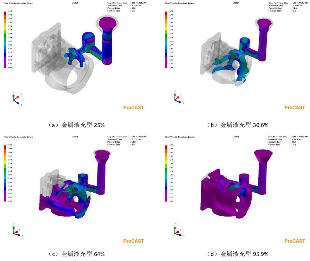
It can be seen from the velocity field shown in the figure that during the whole filling process of the mold cavity, the flow of the molten metal is relatively stable as a whole, and the velocity ratio of the molten metal is not very different, which is not easy to lead to sand washing and sand damage. In Figure (b), a little liquid metal is dispersed, and the molten metal has been filling the cavity. The riser of the main runner plays a role in blocking the sand, thus reducing the possibility of casting defects such as sand holes in the axle housing Sex. It can be seen from figures (b) and (c) that the flow of liquid metal is stable and relatively uniform in the whole filling process, so it can be judged that the scheme is better.