
1.Simulation results and analysis of filling process
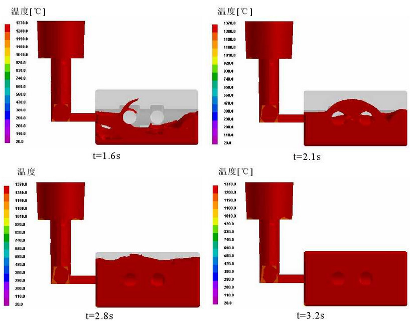
The filling process of the casting is shown in the figure. It can be seen from the figure that when the liquid metal just enters the cavity, i.e. about 1.6s, the filling is not smooth and spatter occurs. However, during the filling process, the casting is gradually smooth, which can effectively prevent the formation of defects such as entrainment gas and slag.The irregularity at the beginning of pouring is mainly due to the introduction of liquid metal into the cavity from the middle of the casting and the impact on the lower surface of the cavity after the liquid metal enters the cavity, resulting in the irregularity of the filling process and spattering.
2.Simulation results and analysis of solidification process
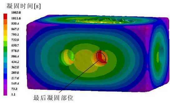
The figure shows the solidification time cloud in the process of valve body casting. It can be seen from the figure that the casting is solidified inwards from all sides. The final solidification position is located on the edge of the intersection between the valve body sinking groove and the outlet. The reason is that the outer surface of the casting is in direct contact with the surface of the casting, with large heat dissipation area, large temperature gradient and easy cooling of the casting to solidify; while the inner surface of the casting is blocked by the outer layer.Separation, small heat dissipation area, small temperature gradient, not easy to cool, resulting in long solidification time.
The diagram shows the distribution of shrinkage voids with porosity greater than 1% (macroscopic shrinkage when porosity greater than 1%) during valve body casting.Porosity is the ratio of the volume of voids in a casting unit to the total volume of the unit.It can be seen from the diagram that shrinkage holes appear near the two edges of the valve body sinking groove near the oil outlet side with the maximum porosity of 91.8%. The shrinkage hole I is located in the middle of the two sinking grooves of the valve body and has irregular shape, with the center 3.2mm away from the edge of the small sinking groove; and the shrinkage hole II is located on the other edge of the small sinking groove and its shape is U-shaped.
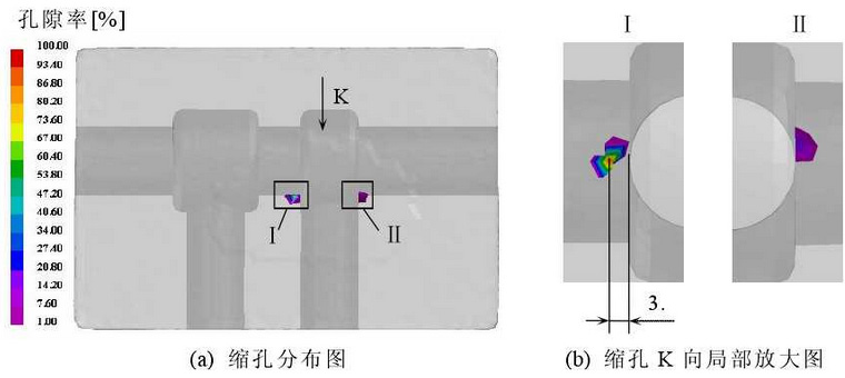
Contrasting with the cloud diagram of solidification time, it can be seen that shrinkage holes occur at the last solidification part of the casting, because during solidification the casting always solidifies from outside to inside. During solidification, an isolated liquid phase region will inevitably be formed, i.e. the liquid phase region to be solidified surrounded by the solidified solid phase shell. As cooling continues, the solidified part only needs to complete the solid phase shrinkage.The liquid phase contraction, volume expansion and solid phase contraction are required in the isolated liquid phase region, and the expansion volume is not enough to compensate for the shrinkage of the metal liquid, and there is no liquid to compensate for the shrinkage, thus resulting in shrinkage holes. In addition, due to the intersection of valve holes, sinking grooves and oil outlets, the heat joint is formed, and the resistance of the casting during shrinkage is large, which is easy to form shrinkage holes.