
The structural diagram of each direction of the tractor reducer box is shown in Figure 1. The mass of the box casting is 205KG and the outer contour dimension of the parts is 912 × 657 X 600mm。
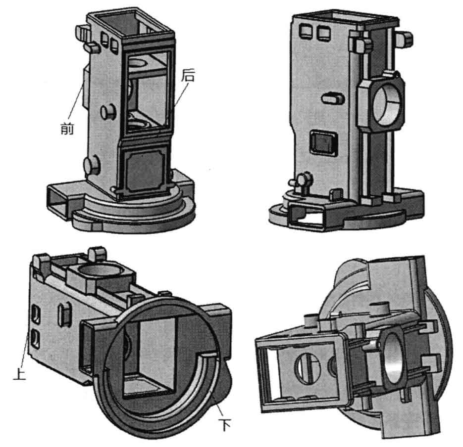
As shown in Figure 1, the overall dimension of the upper end of the box is 467 × 355mm, the lower end is formed by the intersection of a circular boss with a diameter of 600mm and a rectangular boss with a length of 650mm. The overall wall thickness of the reducer box is thin and the structure is complex. During mold filling, liquid metal splashing and unstable mold filling are easy to occur. Due to the thin wall thickness and fast solidification speed, the casting cannot be effectively fed, which may lead to insufficient pouring, cold shut and other defects at the thin wall, shrinkage porosity, shrinkage cavity and other defects at the alternating thin thickness and bulge, and deformation at the large plane and curved surface of the casting.
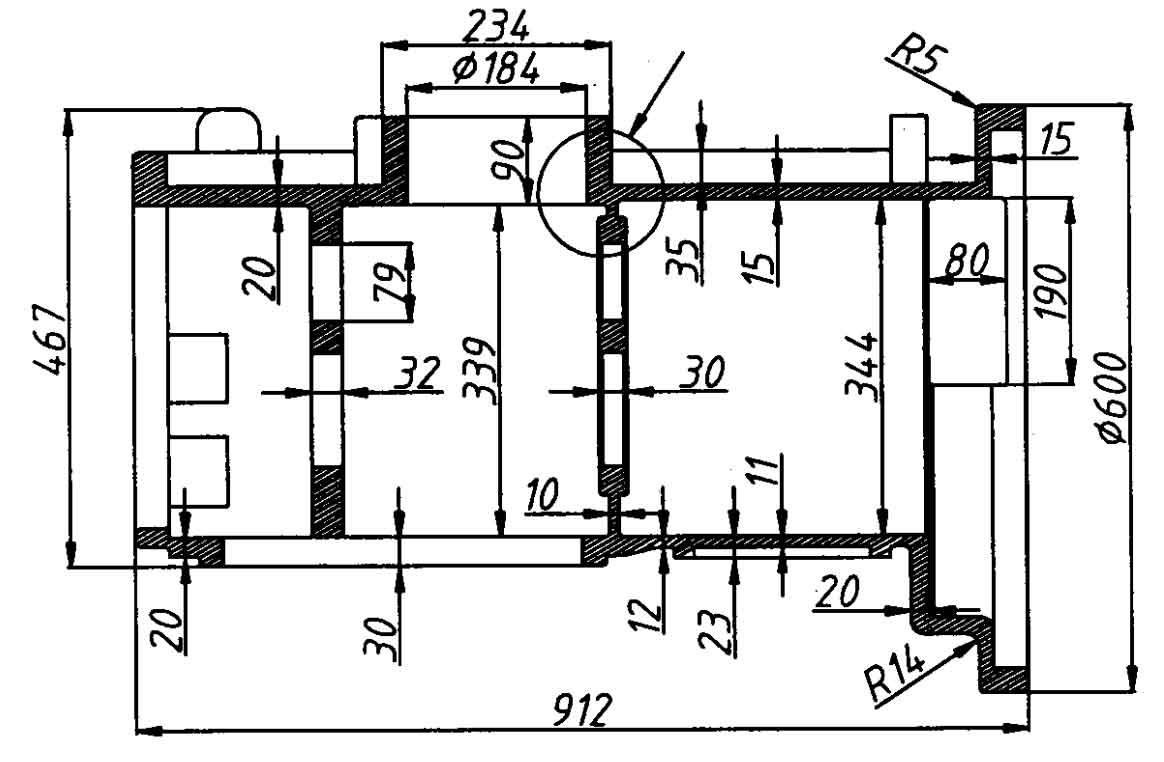
1) Wall thickness analysis
The overall dimension of the tractor reducer case body casting in this paper is 912x657x600mm, as shown in Figure 2. The overall dimension of the upper end of the box is 467x355mm, and the base of the lower end is formed by the intersection of a circular boss with a diameter of 600mm and a rectangular boss with a length of 650mm. The internal structure of the box is complex. Two support plates supporting bearings or shafts are arranged inside the box, and the support plate is provided with installation holes. In Figure 2, the size of thin-wall part of the casting is 10mm and the size of thick wall part is 32mm. The front and rear of the casting are equipped with mounting bosses of bearings or shafts. The height of the front boss is 90mm, the inner diameter is 184mm, the outer width is 234mm, and the wall thickness of the front large plane is 15mm and 20mm. There is a sudden change in thickness at the circular mark in Figure 2, which is easy to form hot joints here. Corresponding measures should be taken in the design of casting scheme. When the wall thickness of the box casting is uneven, the feeding is insufficient at the thick parts or the concession of the core is poor, it is easy to produce shrinkage porosity, shrinkage cavity, crack and other defects at these positions. In the design, the defects are eliminated by changing the casting structure, such as adding stiffeners.
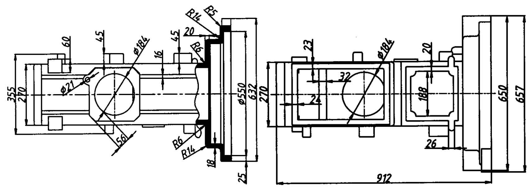
2) Stiffener position
As shown in Figure 3, bosses are set at the upper and lower ends of the casting, and stiffeners are set in front of the casting to connect the lower boss, shaft mounting boss and the boss at the upper end of the casting. The thickness of the stiffeners is 16mm and the width is 35mm. In order to increase the strength of the installation position of the shaft or bearing, a stiffener is added here. The thickness of the stiffener is 11mm and the width is 24mm and 23mm respectively. In order to ensure the quality of the casting and prevent the different crystallization speed of the internal structure during solidification due to uneven wall thickness, shrinkage cavity caused by loose structure at the thick part, or crack at the alternating thin and thick part, the wall thickness of the casting shall be uniform or gradually changed to avoid sudden change of wall thickness and local large thickness. The other two sides of the casting are provided with circular bosses with a thickness of 45mm. The included angle between the stiffener and the casting should not be too small, otherwise it is easy to cause sand inclusion; The included angle between stiffeners should not be connected, otherwise the hot joint at the corner will be more serious. The angle between the casting and the body wall of the gearbox is reasonable.
3) Cast fillet
In order to prevent the hot metal from washing away the sand mold corner and sand falling at the sand mold corner during pouring, and prevent casting defects at the corner of the casting, the intersection of adjacent surfaces on the casting shall be provided with casting fillet.
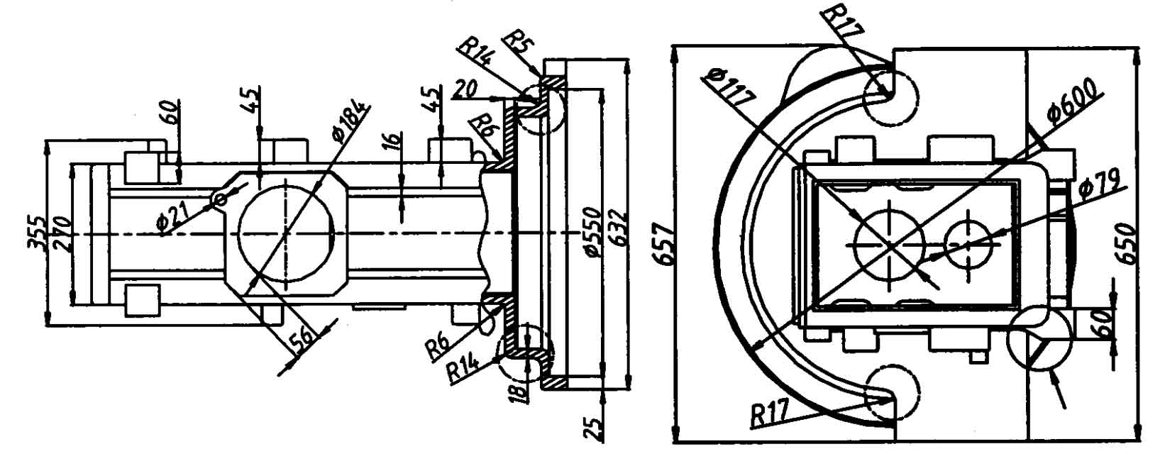
As shown in Figure 2 and Figure 4, the two walls intersect at the circular mark, and there is a hot joint, so the transition fillet can be set at the intersection of the two walls. The radius of transition fillet is determined according to the difference of wall thickness. There is no fixed value. Generally, the radius is 3-10ram. In Figure 4 (a), the fillet radius at the intersection of the two walls of the arc-shaped boss at the lower base of the box is 5mm, 6mm and 14mm respectively; in Figure 4 (b), the fillet radius at the intersection of the arc-shaped boss and the rectangular boss at the lower base of the box is 17mm; the arrow in Figure 4 (b) refers to the transition arc. Since this is the connection between the boss and the wall of the box and there is a sudden change in the wall thickness, setting the transition arc can reduce the occurrence of cracks The possibility of shrinkage porosity and other defects, and the design is more reasonable.
4) Minimum casting hole
For most parts, mounting holes, grooves and other structures are designed on the parts. Whether to cast the mounting holes and grooves directly in the casting process, we should comprehensively consider the economy and the requirements of castings for machining accuracy. Generally, the holes and grooves with large diameter on the casting should be cast directly, so as to reduce metal waste, save processing time, and reduce the hot spots formed by local excessive thickness of the casting; For smaller holes and grooves, it is not suitable to cast, because it is easy to produce sand sticking at the casting hole of the casting, resulting in difficulties in cleaning and processing. Generally, the method of direct processing after casting forming is adopted, which is convenient and efficient; Some holes with specific requirements or holes that cannot be machined must be cast. As shown in Table 4, it is the diameter of non cast hole of gray cast iron. If the hole diameter is less than 30mm (single piece, small batch) or 15mm (large batch), it does not need to be cast. The reducer box body casting in this paper is mass production. As shown in Figure 4 (a), if the hole diameter is 21ram, it needs to be cast.
| Production batch | Minimum casting hole diameter of gray cast iron (mm) |
| Mass production | 12-15 |
| Single piece, small batch production | 30-50 |
| Batch production | 15-30 |