The parts of a motor shell are shown in Figure 1. Due to the special state of working conditions, a large number of heat sinks need to be designed around the sand casting. Generally, the number of heat sinks of a motor shell by sand casting will reach 40 ~ 100, the depth of each heat sink is 100 ~ 120 mm, and the length is about 100 ~ l 800mm according to the size of sand casting, The thickness of each heat sink is 4 ~ 8 mm, and the gap between each two heat sinks is 5 ~ 6 mil; Due to the particularity of the size parameters of the heat sink, in the traditional production mode, each heat sink structure on the sand casting model needs to be made into an independent module as a separate structure, that is, if a motor sand casting has 50 heat sinks, 50 independent heat sink modules need to be made, and each module needs to be assembled in the traditional molding process, After sand filling assimilation, each module needs to be removed from the sand mold, which is not only time-consuming and laborious, but also causes damage in the operation process, affects the shape of the heat sink, and in serious cases, the whole semi-finished product will be scrapped.
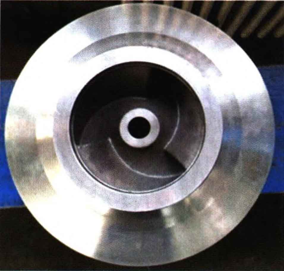
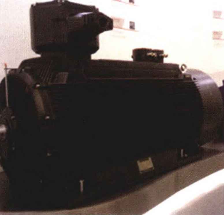
3D printing sand mold is a kind of additive manufacturing technology, which omits the production process of sand mold casting model and directly prints sand mold. 3D printing sand mold does not consider the mold starting inclination of traditional model, and can combine and print complex structures. When producing motor shell with heat sink, the heat sink can be combined and printed in a large area, which can ensure the size of each heat sink, It can also ensure the relative size of each two heat sinks, effectively avoiding the shape taking in the traditional sand casting method, and the casting size fully meets the specification requirements. Figure 2 shows the casting blank after the process improvement, with good appearance quality and smooth streamline of inner cavity and blade arc surface. After rough machining of the casting, no quality problems were found, as shown in Figure 3. Figure 4 shows the dimensional measurement results of castings after process improvement.