
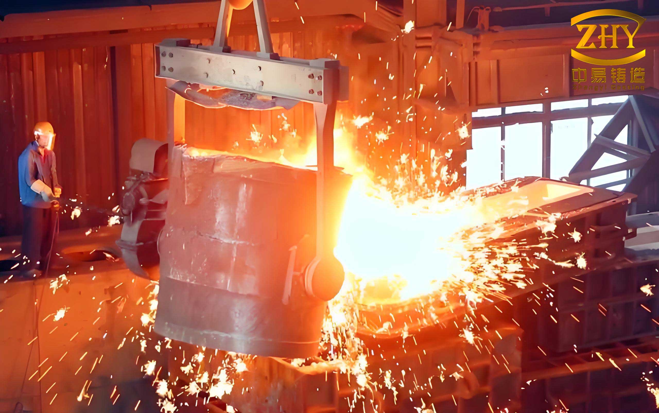
As a key metal forming method, casting serves as a fundamental unit in manufacturing for supplying blanks. However, due to factors such as shrinkage deformation, gating system deviations, and mold wear during the casting process, the actual allowance distribution of casting parts within the same batch exhibits significant non-uniformity, with discreteness reaching millimeter levels. Studies indicate that the allowance dispersion of casting parts can be as high as ±2 mm, directly leading to a reduction in machining efficiency by over 30%. This makes it challenging to achieve efficient allowance control in subsequent machining stages using unified process parameters. With the implementation of the “14th Five-Year Plan” in domestic enterprises, the deep integration of new-generation information technology and manufacturing is accelerating the restructuring of the global industrial competitive landscape. On-machine inspection technology, derived from sensors and data acquisition and processing, involves equipping machine tools with probes or other physical feedback structures to detect the actual machining dimensions of parts and automatically compensate machining paths based on measurement results. This article aims to analyze the transformation of batch automated manufacturing processes for ship casting parts in an intelligent environment. Drawing on our company’s experience in automated machining of typical casting parts, we explore the deep integration of on-machine inspection, digital models, and CNC programs to achieve an automated machining mode of “modeling-inspection-compensation-machining.” This provides theoretical support and practical reference for enterprises’ intelligent leap, contributing to the high-quality development of the manufacturing industry.
The automation architecture is designed from three dimensions: platform, technology, and implementation. We build a collaborative model to create an intelligent manufacturing process production system for the manufacturing department, enabling large-model operation and achieving set goals. The automation framework integrates various technologies to address core issues such as discrete allowances, non-fixed machining programs, and human intervention in casting part machining.
Automated machining, as a key manifestation of the Fourth Industrial Revolution, features a multidisciplinary integrated technical system. It primarily encompasses key technologies such as digital modeling and process analysis, on-machine inspection, wear prediction, and the integration of intelligent technologies with CNC. Firstly, digital modeling and process analysis involve constructing 3D digital models to complete process planning and simulation, enhancing process safety and effectively guiding actual production. Secondly, on-machine inspection and wear prediction technologies can replace operators in auxiliary measurements and continuous monitoring during machining, effectively reducing auxiliary process time and labor intensity. Additionally, the integration of intelligent technologies with CNC incorporates on-machine inspection, wear prediction, and intelligent error-proofing into machining programs, reducing low-level errors and driving machine tools toward automated machining.
Digital modeling transforms 2D drawings into 3D visual models, enabling full-process visualization from design and development to production and maintenance. For instance, Airbus A350 uses digital assembly models to reduce wiring installation errors by 50%. With this technology, operators can intuitively observe part structures and efficiently plan manufacturing processes based on machining features. Virtual commissioning allows process verification and risk prediction before production, identifying potential machining issues in advance and shortening development cycles. Moreover, by leveraging our company’s cutting data network, we can quickly match machining parameters similar to part machining conditions (material,工况, machining stage, tool used, and machine tool rigidity), reducing on-site debugging time and facilitating efficient machining of casting parts.
On-machine inspection is an emerging technology based on sensors and data acquisition and processing, operating in real-time on machine tools. It integrates high-precision probes and sensors to directly collect data on workpiece dimensions and surface topography during machining, comparing them with digital models in real-time. This eliminates the disassembly, transportation, and other steps of traditional offline inspection, shortens auxiliary process time, reduces the workload of operators in auxiliary measurements, and enables a one-person-multiple-machines model. Meanwhile, feedback control based on online measurement data can实时修正刀具磨损、热变形等工艺偏差, effectively controlling dimensional accuracy in finish machining and improving the qualification rate of precision casting parts.
Since the core probe of on-machine inspection is mounted on the machine tool, similar to machining tools, and inspection data is based on the Cartesian coordinate system built by the machine tool, environmental factors affecting machine tool accuracy also impact on-machine inspection accuracy. Limited by machine tool thermal deformation, environment, and temperature, the real-time accuracy of on-machine inspection cannot be generalized based on equipment specifications. For example, Renishaw probe on-machine inspection systems may have a repeatability of ±1 μm, but in practice, machine tool thermal deformation can increase measurement error by 0.02–0.05 mm. Enterprises must pay special attention to this when implementing on-machine inspection for casting parts.
Wear prediction is a key technology in advanced manufacturing, playing a significant role in automated machining. Currently, there are two main prediction methods. One involves installing sensors on the machine tool spindle or relevant positions to monitor cutting vibrations, converting monitored data frequencies (vibration or current) into signals, and using integrated algorithms to learn tool vibration curves. Valid data is stored as standard samples for comparison with subsequent parts under similar conditions. When the set vibration curve exceeds the standard curve threshold, the machine tool alarms or stops. Relevant studies show that this method can achieve an accuracy of 85% in predicting tool life for nickel-based alloys. This mode, requiring extensive experience, is often used for batch part machining, effectively reducing on-site auxiliary workload for operators. The other method is empirical prediction, which estimates tool wear standard values based on tool切削磨损 cycles, categorizing feature machining programs and tools accordingly. This mode responds quickly and has lower requirements for software and hardware, making it suitable for small-batch production modes and discrete manufacturing enterprises involved in casting part production.
The essence of wear prediction technology is judging cutting conditions based on empirical values. In the field of cutting machining, many factors affect cutting conditions, such as tool overhang and workpiece material differences. In practical applications, false alarms are the most apparent issue. Balancing prediction accuracy and timeliness, and finding the optimal solution between early warning and accurate prediction, is a challenge every enterprise must face when applying this to casting parts.
Intelligent technologies include on-machine measurement, tool monitoring, and intelligent error-proofing. The application subject is the CNC program that drives machine tool machining. Data generated from on-machine monitoring and standard values from tool monitoring are archived, and error-proofing statements for tool diameter and variable confidence intervals are reflected in the CNC program. Currently, there are two common integration methods. One is to place all inspection, machining, and error-proofing information in a single CNC program. In this mode, the number of programs is minimal, facilitating management and调用 by technicians and operators. The other is modularizing various data, creating individual subprograms for inspection, machining, and error-proofing information, and integrating them into a main program in a modular manner for调用. In this mode, each function has strong identifiability, allowing easy adjustment of individual functional modules and enabling rapid response.
The deep integration of intelligent technologies and CNC programs requires converting collected data into variables recognized by CNC programs. A common practice is to call the variable intervals set by the machine tool, such as the R-series variables in Siemens systems. However, during application, directly using R variables poses certain risks. Since CNC machines generally embed fixed cycles (e.g., drilling, milling slots), some R variables are also used in the background of these modules. Therefore, if R variables are directly used for data conversion in intelligent technologies, abnormalities may occur when the machine tool’s built-in cycles are used, and in severe cases, overcutting or collisions may happen, especially when machining complex casting parts.
Our company uses intelligent manufacturing workshops as a carrier to implement a digital-intelligent process system based on the characteristics of discrete enterprises. Facing bottlenecks encountered during implementation, we propose corresponding strategies and complete practical verification, solving core issues such as discrete allowances in casting part blanks, non-fixed machining programs, and human intervention, achieving the goal of automated production for casting parts.
We selected a typical part: a gas turbine整流支柱 made of K446, a nickel-based precipitation-hardening superalloy, which is a typical difficult-to-cut material. The blank form is a casting part, requiring machining of external shapes and hole systems in milling operations. Due to uneven allowances in casting parts, milling processes require operator intervention for control, leading to high milling times. Initially, machining time per piece was 96 hours, including 46 hours of cutting time and 50 hours for tasks such as blank measurement, accuracy control, and auxiliary tool changes. With the application of intelligent manufacturing technologies in workshops, the introduction of new functions like on-machine measurement, automatic measurement, and automatic tool changes has promoted process improvements and reduced auxiliary time. For milling the external shape of the整流支柱, aiming to improve machining efficiency and reduce frontline operator workload, we implemented automated machining by integrating new functions.
The implementation platform setup in our company’s intelligent manufacturing workshop is detailed in the table below.
| Name | Function |
|---|---|
| Equipment | |
| Four-axis machining center (HEC1250) | Process machining machine tool |
| Software | |
| NX8.5 | 3D modeling and CAM programming |
| VERICUT7.2 | Machining simulation |
| Renishaw on-machine measurement system | On-machine inspection |
During the initial implementation phase, we defined the implementation goals as: completing on-machine inspection of blank allowances, automatic compensation for high-precision features, and achieving automated operation of part milling programs. Based on these goals, we established the process as: process analysis → accuracy verification → tool wear verification → logic control → machining simulation → compensation machining.
First, process analysis involves arranging automated machining processes based on the entire part’s machining features and accuracy. For example, the part process arrangement considers all features of the casting part. Second, accuracy verification tests the actual accuracy of on-machine measurement by comparing it with manual measurement tools. Test measurement data comparison is shown in the table below.
| Test Feature | On-Machine Measurement (mm) | Manual Tool (mm) | Error (mm) |
|---|---|---|---|
| Plane 115 | 115.05, 115.03 | 114.99 | 0.06 |
| Outer circle φ86 | 86.03, 86.02, 86.02, 86.00 | 86.00 (micrometer) | 0.03 |
| Side wall 340 | 340.03, 340.01, 339.99 | 339.99 | 0.03 |
From the data, the actual error in on-machine measurement is 0.06 mm in the spindle direction and 0.03 mm in the vertical direction. Based on this accuracy range, we determined the sequence of automated processes for the casting part.
Third, tool wear verification ensures that automated operation is based on the idea that tools can complete normal machining for a single program without tool wear significantly affecting part dimensions or quality. According to the material characteristics of the casting part, we developed milling programs and explored tool wear conditions to determine tool implementation strategies. Rough milling tool wear conditions are summarized in the table below.
| Sequence | Machining Feature | Tool Used | Wear Condition | Dimensional Error (Digital Display) (mm) |
|---|---|---|---|---|
| 1 | Rough mill 115 | φ63 mm fast-feed mill | Tool tip rake wear | 0.12 |
| 2 | Rough mill 113 | φ63 mm fast-feed mill | Tool tip rake wear | 0.12 |
| 3 | Rough mill 113-115 | φ40 mm square-end mill | Tool tip rake wear | 0.08 |
| 4 | Rough mill 330 | φ63 mm fast-feed mill | Tool tip rake wear | 0.06 |
| 5 | Rough mill 237 end face | φ63 mm fast-feed mill | Tool tip rake wear | 0.25 |
| 6 | Rough mill 26 inner stop | φ20 mm R1.2 mm mill | Tool tip rake wear | 0.3 |
| 7 | Rough mill 600 face | φ63 mm fast-feed mill | Tool tip rake wear | 0.06 |
| 8 | Rough mill φ86 blank | φ12 mm square-end mill | Tool tip rake wear | 0.1 |
| 9 | Rough mill M72 inner hole | φ40 mm square-end mill | Tool tip rake wear | 0.05 |
| 10 | Rough mill 599 face | φ63 mm fast-feed mill | Tool tip rake wear | 0.05 |
| 11 | Drill M12 bottom hole | φ8.5 mm drill | No significant wear | – |
| 12 | Expand M12 bottom hole | φ10.2 mm drill | No significant wear | – |
| 13 | Drill D20 mm milling hole | φ10.2 mm drill | No significant wear | – |
| 14 | Expand D20 mm bottom hole | φ14 mm drill | No significant wear | – |
| 15 | Drill D20 mm bottom hole | φ10.2 mm drill | No significant wear | – |
| 16 | Expand D20 mm bottom hole | φ14 mm drill | No significant wear | – |
| 17 | Mill 4×C2 chamfer | 45° chamfer mill | No significant wear | – |
| 18 | Mill 2×C5 chamfer | 45° chamfer mill | No significant wear | – |
| 19 | Rough open D72 mm | D28 mm three-side edge mill, thickness 3 mm | Tool tip rake wear | 0.11 |
| 20 | Under-cut | D28 mm three-side edge mill, thickness 3 mm | No significant wear | – |
| 21 | Mill D74 mm step face | D40 mm square-end mill | Tool tip rake wear | 0.06 |
The experimental results are consistent with findings from literature. Using a wear threshold of 0.06 mm as a基准, tools with wear less than 0.06 mm are grouped, and programs with tool breakage are split to ensure smooth operation of individual programs for casting parts.
Fourth, logic control is essential because the casting part features have high precision, and based on tool wear effects, deviations caused by tool cutting wear exceed feature dimensional tolerances. To control dimensional accuracy formed by automated machining, online measurement is interspersed between rough and finish machining, with dimensional accuracy compensation based on measured values. Relevant logic is edited through CNC programs. For the casting part, we designed two commonly used logic judgment controls.
For rough machining stages, functions such as allowance measurement input and automatic tool change are required. The control program is designed as follows (in pseudo-code for illustration):
T="X63"
TCH ; automatic tool change
M3 S220
AA:
G0 X=-213.6+1 Y=R2
Z=R360 ; allowance calling address
G1 F100 Y=-R2 M8
G0 Z200
STOPRE
R360=R360-0.1
IF R360>0.1 GOTOB AA
For finish machining stages, functions such as allowance measurement and automatic compensation are required. A “1+1″双层控制结构 is designed as follows:
N1 T="MT"
N2 TCH
N3 G55 G0 B0
N4 X-55 Y=138.9/2
N6 TRANS Z=213.6+24
N7 Z50
CYCLE977(200xx,,,1,….01,,,,,1,1) ; measure feature status
N8 R378=_OVR[16] ; allowance calling address
N9 G0 Z1200
IF R378>0.01 ; allowance logic judgment
CALL "S_11_JX_340_1.MPF"
ELSE ; allowance logic judgment
IF R378<(-0.1)
MSG("Allowance abnormal")
GOTO BB
M09
TRANS
BB:
M30
Through these two logic structures, the allowance data measured for the casting part is integrated into the machining CNC program, achieving automatic compensation for feature accuracy.
Fifth, machining simulation involves importing 3D models and machining programs into simulation software to simulate measurement, cutting, and program jumps, ensuring safety and reliability. Sixth, compensation machining involves actual加工调试 after simulation to verify the feasibility of the designed process and measurements. The machined casting part is inspected for quality.
Through the implementation of automated processes, we successfully completed milling operations for the casting part, significantly improving the machining cycle. Operators no longer need to intervene during cutting. After implementation, the actual time decreased from 96 hours to 48 hours, cutting time reduced from 46 hours to 44 hours, and auxiliary time dropped from 50 hours to 4 hours, greatly reducing frontline operator auxiliary time for casting part machining.
In conclusion, through the implementation of automated processes for typical casting parts, we have verified the feasibility of integrating on-machine inspection probes with digital modeling and CAM programming. This forms a full-process solution of “inspection-analysis-compensation” for ship casting parts, enabling a transformation from “experience-driven” to “data-driven” machining of casting parts. It significantly reduces frontline operator intervention during workpiece machining, injecting new momentum into the reform of the “one-person-multiple-machines” machining model.
To further elaborate on the technical aspects, we can formalize some concepts with formulas. For instance, the allowance compensation can be modeled as a feedback control system. Let the desired dimension be $D_{target}$, the measured dimension be $D_{measured}$, and the compensation value be $C$. Then, the error is calculated as:
$$ E = D_{target} – D_{measured} $$
The compensation $C$ is then applied to the tool path offset, often using a proportional control:
$$ C = k_p \cdot E $$
where $k_p$ is a proportional gain factor, typically set based on machine tool and process characteristics. For high-precision casting parts, we might use more advanced control laws, such as PID (Proportional-Integral-Derivative), but in practice, simple proportional compensation is often sufficient for milling operations.
Regarding tool wear prediction, empirical models can be derived. Tool wear $W$ over time $t$ can be approximated by a linear or exponential function. For example, a linear wear model for cutting tools in casting part machining might be:
$$ W(t) = a \cdot t + b $$
where $a$ is the wear rate and $b$ is the initial wear. From our data, we can estimate $a$ for different tools. For instance, from the table, the φ63 mm fast-feed mill shows wear of 0.12 mm over a certain cutting time. If we denote cutting time per feature as $t_c$, then the wear rate $a$ can be computed as:
$$ a = \frac{\Delta W}{t_c} $$
This allows us to predict when tool replacement is needed, ensuring consistent quality in casting part machining.
Additionally, the integration of digital models enables simulation-based optimization. The machining force $F$ can be estimated using models such as:
$$ F = K_s \cdot a_p \cdot f_z \cdot z $$
where $K_s$ is the specific cutting force, $a_p$ is the depth of cut, $f_z$ is the feed per tooth, and $z$ is the number of teeth. For casting parts made of materials like K446, $K_s$ is higher, requiring careful parameter selection to avoid excessive tool wear.
In terms of implementation, we have developed a comprehensive table summarizing key parameters for automated machining of casting parts, as shown below.
| Parameter Category | Typical Value for Casting Parts | Impact on Automation |
|---|---|---|
| Allowance dispersion | ±2 mm | Requires adaptive compensation |
| On-machine inspection accuracy | ±0.03-0.06 mm | Limits compensation precision |
| Tool wear rate (roughing) | 0.05-0.3 mm per feature | Needs periodic monitoring |
| CNC program variables | R-series or custom | Enables logic control |
| Machining time reduction | Up to 50% | Improves efficiency |
Furthermore, the economic benefits can be quantified. Let $T_{old}$ be the old machining time, $T_{new}$ be the new machining time, and $C_{labor}$ be the labor cost per hour. The cost saving per casting part is:
$$ \Delta C = C_{labor} \cdot (T_{old} – T_{new}) $$
For our case, $T_{old} = 96$ hours, $T_{new} = 48$ hours, so if $C_{labor} = \$50/hour$, then $\Delta C = \$50 \cdot 48 = \$2400$ per part. This demonstrates the significant cost efficiency of automated machining for casting parts.
In summary, the automated machining technology for ship casting parts, based on on-machine inspection and digital modeling, represents a paradigm shift in manufacturing. By addressing the inherent variability in casting part allowances, we achieve higher precision, reduced labor, and improved throughput. The integration of technologies such as digital twins, real-time monitoring, and intelligent CNC programming paves the way for smarter factories. As we continue to refine these methods, we anticipate further advancements in the machining of complex casting parts, contributing to the broader goals of industrial automation and sustainability.