
When the number of faulty bucket teeth is 2, the idea is similar to that of a faulty bucket tooth. It can also be discussed in two cases. The first is that one of the bucket teeth of the fault appears at both ends. This situation can be divided into two small cases:
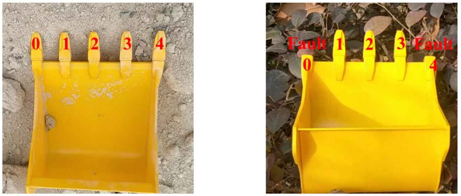
The most special case is that the bucket teeth at both ends are broken. This situation can be judged through the bucket tooth calibration. As shown in Figure 1, when the bucket teeth 0 and 1 of the normal bucket in Figure 1 (a) cannot match the bucket teeth in Figure 1 (b), the bucket teeth at both ends are faulty.
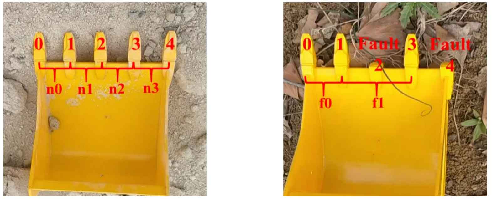
When the fault position of one bucket tooth is at one end and the fault position of the other bucket tooth is in the middle, in this case, it is necessary to calibrate one of the bucket teeth at both ends, and the rest can be discussed according to the situation of one bucket tooth fault. As shown in Fig. 2, the bucket tooth 0 in Fig. 2 (a) can be matched with the bucket tooth 0 in Fig. 2 (b) through the program. At this time, it can be judged that the bucket tooth 4 in Fig. 4-25 (b) is faulty. Next, determine another faulty bucket tooth through the spacing. For Fig. 2 (b), the total spacing of the detected bucket teeth is F0 + F1, while for the normal bucket in Fig. 2 (a), the last bucket tooth spacing N3 needs to be removed. At this time, the total spacing of the remaining bucket teeth in Fig. 2 (a) is N0 + N1 + N2, and the proportion of N0 in the total spacing of the remaining bucket teeth is about equal to the proportion of F0 in the total spacing of the bucket teeth, The proportion of N1 or N2 in the total spacing of the remaining bucket teeth is less than that of F1 in the total spacing of the bucket teeth.
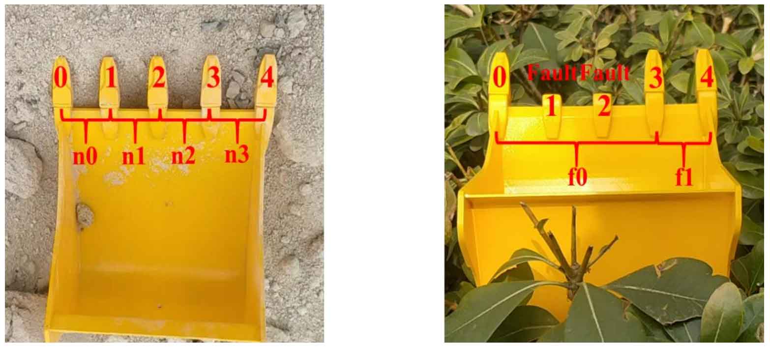
In the above fault conditions, there is a situation that needs to be explained, that is, the position of the fault bucket tooth in the middle is just next to the fault end bucket tooth, which should be classified as a special case, that is, determine the fault bucket tooth at the end first, and then determine the fault bucket tooth according to the proportion of spacing. As shown in Figure 3, first locate the faulty bucket tooth 0 in Figure 3 (b). For Fig. 3 (a), N0 and N1 are removed from the total spacing of bucket teeth, and then the ratio of N2 and N3 to the remaining spacing is used to compare the ratio of F0 and F1 to the total spacing. If they are similar, the faulty bucket teeth can be determined.
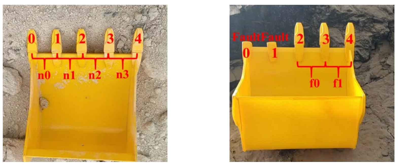
The second case is that the two broken bucket teeth are located in the middle part. In this case, the fault bucket teeth can be calibrated as long as the spacing between bucket teeth becomes larger. As shown in Figure 4, after the bucket teeth are detected through the target detection program, the bucket teeth 0 and 4 of the normal bucket are matched with the bucket teeth 0 and 4 of the faulty bucket respectively. In Figure 4 (b), the proportion of F0 in the bucket tooth spacing is greater than the proportion of N0, N1 and N2 in the total bucket tooth spacing, and also greater than the proportion of (N0 + N1) and (N1 + N2) in the total bucket tooth spacing, which is approximately equal to the proportion of (N0 + N1 + N2) in the total bucket tooth spacing. Therefore, it can be obtained that the position of the faulty bucket tooth is bucket tooth 1 and bucket tooth 2.
Through the target detection program, the position of the normal bucket teeth in the image can be obtained, and the return form is the pixel coordinates of the lowest vertex and the highest vertex of the detection frame. After locating the fault bucket teeth above, we can get the sequence of the fault bucket teeth.