

1. Introduction
The crankshaft is a crucial component in engines, and its quality and reliability directly affect the performance and safety of the entire engine system. In this study, we focus on the defect analysis of a QT900 – 5 ductile iron casting crankshaft used in a mining vehicle. The crankshaft suddenly fractured at the 7th and 8th cranks after 1,269 hours of operation, which led to severe consequences. Understanding the causes of such failures is essential for improving casting quality and preventing similar incidents in the future.
2. Experimental Instruments and Methods
- Instruments: HX – HW8B high – frequency infrared carbon – sulfur analyzer, Plasma 3000 ICP spectrometer, Hitachi S3400N scanning electron microscope, JED – 2200 energy spectrometer,metallurgical microscope, E45 – 305 electronic universal material testing machine, THBS – 3000DD Brinell hardness tester.
- Methods: Chemical composition analysis was performed using relevant national standards. Macroscopic analysis involved observing the fracture surface morphology. Scanning electron microscopy and energy spectrometry were used to analyze the microstructure and elemental composition of the defects. Microscopic structure analysis was carried out through metallographic and SEM examinations. Performance testing was conducted to evaluate the mechanical properties of the crankshaft material.
3. Experimental Results and Analysis
- Chemical Composition Analysis: The chemical composition of the failed crankshaft met the technical requirements, as shown in the following table.ElementTechnical Requirement (w/%)Measured Value (w/%)C3.60 – 3.903.64Mn0.30 – 0.500.5Si1.90 – 2.402.16P≤0.0600.017S0.004 – 0.020.004Cr≤0.100.04Mg0.02 – 0.060.04Ce≤0.0250.005Cu0.40 – 0.600.55
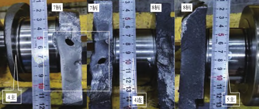
- Macroscopic Analysis: The fracture of the 7th crank originated from the intersection of the 7th crank and the 4th connecting rod lower dead center roll groove edge. The crack source was a hole – like defect, approximately 3mm × 7mm, with a distinctively large volume and a radiating pattern. The 8th crank fracture was brittle and instantaneous. The following images illustrate the fracture morphologies.
- Scanning Electron Microscopy Analysis: The hole in the 7th crank consisted of two small holes with smooth walls. The bottom of the hole was dark, and the main elements in the dark substance were C, O, and Fe. The 8th crank near the 4 – link fillet showed cleavage fracture and a mixed fracture morphology in the middle region.
- Microscopic Structure Analysis: The graphite around the hole in the 7th crank had a good spheroidization level and uniform distribution. The microstructure near the hole consisted of lamellar pearlite, a small amount of ferrite, and graphite. The bottom of the hole and the protrusion area also had oxide layers. The microstructure of the protrusion area showed severe graphite deformation and the presence of martensite.LocationGraphite Spheroidization LevelMicrostructure CompositionOxide Layer PresenceHole in 7th Crank2Lamellar pearlite + a small amount of ferrite + graphiteYesProtrusion Area in 7th Crank–Yes
- Performance Testing: The mechanical properties of the crankshaft material met the technical requirements, as shown in the following table.PropertyYield Strength (MPa)Tensile Strength (MPa)Elongation (%)Hardness (HBW)Measured Value5219167.4302Technical Requirement≥460≥820≥4.5250 – 320
4. Discussion and Improvement Measures
- Defect Cause Analysis: The casting defect in the 7th crank was identified as an invasive air hole. Gas from the sand mold and core sand, such as water vapor, carbon monoxide, and carbon dioxide, entered the casting surface at the intersection of the 7th crank and the 4th connecting rod lower dead center roll groove edge, forming the hole. This invasive air hole reduced the fatigue strength of the crankshaft. When the vehicle was under full load, the stress exceeded the fatigue limit at the defect location, leading to the rapid fracture of the 7th crank. Subsequently, the 8th crank experienced instantaneous overload and failure due to the inertia of the crankshaft.
- Improvement Measures:
- Control the content and moisture of gas – generating substances in the molding sand and core sand: The volatile content of the molding sand should be controlled within 2.3 – 2.5 for ductile iron casting. Daily testing and timely adjustment of the sand ratio are necessary.
- Increase the depth of gas holes: Adjust the parameters of the automatic gas hole punching machine to increase the depth of gas holes on the sand mold surface to 30mm, enhancing the gas exhaust ability of the sand mold.
- Manage furnace charge quality: Ensure that the furnace charge is dry and free of rust. Increase the standing time of high – temperature molten iron during melting, raise the temperature of the electric furnace to 1500 – 1520°C and hold for 3 – 5 minutes. Increase the slag removal times of the molten iron after spheroidization from 2 to 3 times.
5. Conclusion
This study comprehensively analyzed the defect of a QT900 – 5 ductile iron casting crankshaft. The invasive air hole at the intersection of the 7th crank and the 4th connecting rod fillet was determined as the main cause of the crankshaft fracture. Based on the analysis results, corresponding improvement measures were proposed. Future research will focus on further optimizing the crankshaft casting process, improving casting quality, and enhancing the reliability and durability of the crankshaft.