
In the rapidly evolving field of marine and lacustrine development, dredging operations have become increasingly critical, driving demand for high-performance equipment such as large dredge pumps. The impeller, a core component of these pumps, is subject to stringent quality requirements due to its complex geometry and operational stresses. However, during the casting process, various casting defects frequently arise, compromising the impeller’s integrity and functionality. As a practitioner in this industry, I have extensively studied these issues and implemented strategies to mitigate them. This article delves into the common casting defects encountered in large dredge pump impellers, analyzes their root causes, and presents effective countermeasures, supported by technical formulas and tables. Our goal is to enhance casting quality, ensuring reliability and efficiency in dredging applications.
The manufacturing of large dredge pump impellers typically involves sand casting using resin-bonded molds, a method chosen for its flexibility in producing intricate shapes. Despite advanced techniques, casting defects remain a persistent challenge, often stemming from thermal dynamics, material properties, and process control. In our foundry, we have observed that defects like shrinkage porosity, gas holes, sand inclusions, and cold shuts can significantly reduce yield rates. Through systematic analysis and iterative improvements, we have elevated the qualification rate of impeller castings to over 90%. Below, I detail the specific casting defects, their mechanisms, and the strategies we employ to address them.
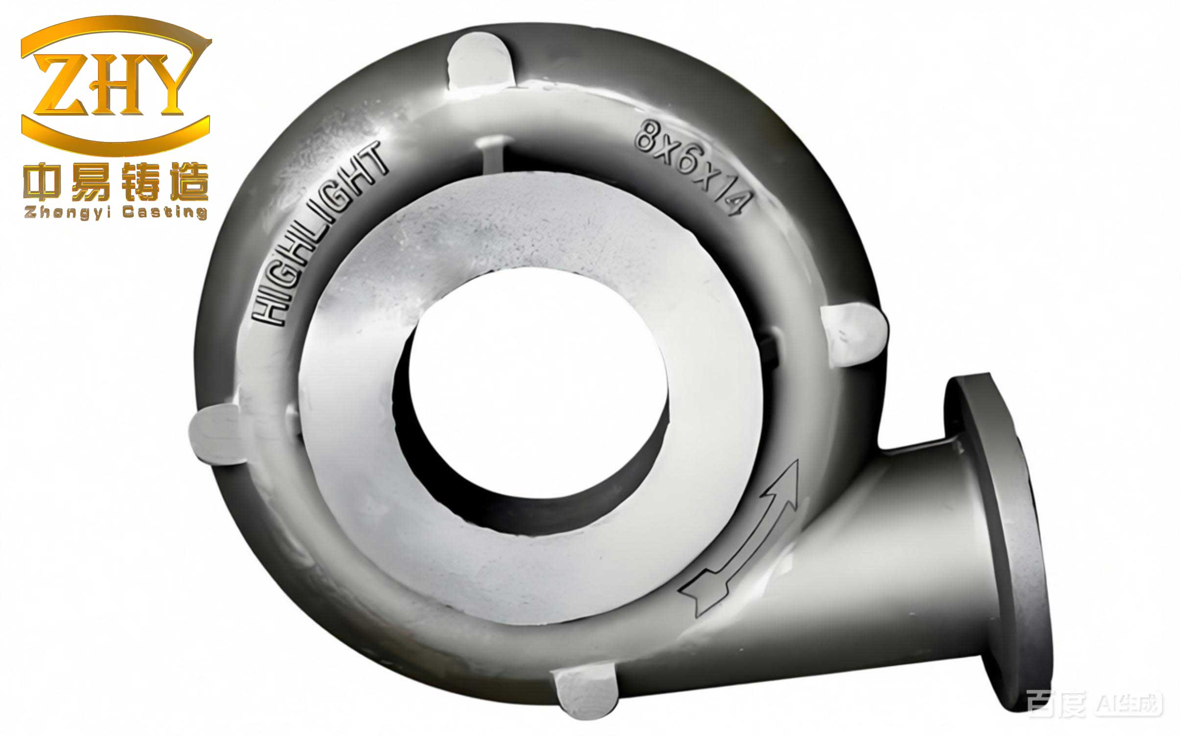
Shrinkage Porosity and Cavities at the Riser Necks of Impeller Hubs and Cover Plates
One of the most prevalent casting defects in large impellers is shrinkage porosity and cavities, particularly at the riser necks of the hub (axis head) and cover plates. The hub section, with a wall thickness of approximately 200 mm, constitutes a significant thermal mass, creating a large hot spot that demands substantial molten metal for effective feeding. Conventional riser designs often fall short in providing adequate feed metal, leading to shrinkage defects. The efficiency of a riser can be quantified using the Chvorinov’s rule for solidification time, where the feeding requirement is related to the volume-to-surface area ratio. For a cylindrical riser, the solidification time \( t \) is given by:
$$ t = k \left( \frac{V}{A} \right)^2 $$
where \( V \) is the volume, \( A \) is the surface area, and \( k \) is a constant dependent on mold material. Inadequate riser dimensions result in premature solidification, causing shrinkage. To combat this, we replaced standard risers with exothermic risers, which generate heat to prolong liquid state, enhancing feeding capacity. The optimal riser height \( H \) for impellers like the 700WN and 800WN models is critical; we enforce \( H \geq 500 \) mm for 700WN and \( H \geq 600 \) mm for 800WN. Additionally, post-pouring, we wait 5–10 minutes before topping up the riser with molten metal and applying exothermic cover agents to minimize heat loss. The effectiveness of this approach is summarized in Table 1.
| Defect Type | Root Cause | Countermeasure | Key Parameters |
|---|---|---|---|
| Shrinkage porosity at hub | Large thermal mass, insufficient feeding | Use exothermic risers, control riser height | Riser height ≥500 mm (700WN), ≥600 mm (800WN) |
| Shrinkage at cover plate riser neck | High sand temperature, gas evolution | Replace sand riser seat with ceramic-formed seat, use exothermic risers | Ceramic seat耐火度 >1600°C |
Adhesion Sand, Gas Holes, Shrinkage at the Intersection of Blades and Cover Plates
Another common set of casting defects occurs at the圆弧 roots where blades, shrouds, and cover plates intersect. These areas are prone to adhesion sand, gas holes, and micro-shrinkage due to sharp corners or insufficient fillet radii, which elevate local heat concentration and gas entrapment. Excessive resin addition in mold sand exacerbates gas generation, leading to chemical sand adhesion and porosity. The gas pressure \( P_g \) evolved during pouring can be estimated by:
$$ P_g = \frac{nRT}{V} $$
where \( n \) is moles of gas, \( R \) is the gas constant, \( T \) is temperature, and \( V \) is volume. Reducing resin content lowers \( n \), mitigating gas defects. Our measures include increasing fillet radii per design specifications to eliminate sharp corners, strictly controlling resin addition to below 2% for impellers up to 700WN, and using chromite sand in these regions for its high chilling power and耐火度. Post-molding, we employ hot-air drying at 120–150°C for 4–6 hours via a pipe inserted into the cavity, ensuring thorough dehydration. Enhanced coating application and manual打磨 of fillets with gauge templates further ensure quality.
Sand Inclusions and Slag Holes on Machined Surfaces of Cover Plates and Hub Faces
Sand inclusions and slag holes are casting defects that manifest after machining, primarily due to residual loose sand from core assembly or low mold surface compactness. During pouring, molten metal冲刷 dislodges sand particles, which become embedded in the casting. To address this, we emphasize mold surface compaction to achieve a hardness above 85 on the scale. We introduce three sand-collection holes at the lowest points of the lower mold cavity to trap loose sand, preventing its ingress. Additionally, specialized ceramic浇道 are used to isolate molten metal from sand-filled runners, and slag traps are added at runner ends. The relationship between sand inclusion probability \( P_s \) and mold hardness \( H_m \) can be expressed as:
$$ P_s \propto \frac{1}{H_m} $$
Thus, higher compactness reduces defect likelihood. Table 2 summarizes these strategies.
| Defect | Causes | Solutions | Control Standards |
|---|---|---|---|
| Sand inclusions on machined faces | Loose sand from cores, low mold hardness | Enhance compaction, add sand-collection holes | Mold hardness ≥85, sand holes at cavity bottom |
| Slag holes | Slag entrainment from runners | Use ceramic runners, install slag traps | Ceramic runner耐火度 >1500°C |
Cold Shuts at the Outlet and Outer Rim of the Front Cover Plate
Cold shuts, characterized by incomplete fusion of metal streams, are casting defects often seen at the impeller outlet and front cover periphery. This arises from prolonged pouring times, low molten metal temperature, or insufficient metallostatic head causing flow interruption. The critical velocity \( v_c \) for avoiding cold shuts depends on temperature and surface tension, approximated by:
$$ v_c = \sqrt{\frac{2 \gamma}{\rho \delta}} $$
where \( \gamma \) is surface tension, \( \rho \) is density, and \( \delta \) is wall thickness. To prevent cold shuts, we strictly control pouring time \( t_p \) based on impeller weight, typically keeping \( t_p \leq 60 \) seconds for large castings. The metallostatic head \( h \) is maintained above 200 mm, and a basin-shaped pouring cup is utilized to ensure continuous flow. Process cards specify these parameters, with supervisors monitoring compliance.
Other Prevalent Casting Defects and Their Mitigation
Beyond the above, several other casting defects impact impeller quality. Non-uniform flow passage width stems from dimensional inconsistencies in fiberglass core boxes or operator errors. We enforce strict dimensional checks using templates, with technicians verifying key dimensions before production. During core assembly, inspectors measure and record each core’s size, ensuring tolerance within ±1.5 mm. Cracks at the cover plate outer rim are attributed to excessive sulfur or phosphorus content in the iron or premature shakeout. We limit sulfur and phosphorus to below 0.03% and 0.05%, respectively, and implement extended mold retention times: for impellers above 700WN, we maintain a holding time of at least 8 days, with压铁 applied 5 hours post-pouring and gradual mold loosening after 24 and 48 hours. Shakeout occurs only when temperature drops below 300°C, avoiding thermal stress cracks. Static balance deviation, a critical quality metric, often results from uneven wall thickness or machining基准 misalignment. We optimize pattern accuracy and coordinate with machining teams to define基准 locations and weight removal zones, ensuring balance corrections are minimal.
The interplay of these casting defects can be analyzed through defect density models. For instance, the overall defect rate \( D \) might be expressed as a function of multiple process variables \( x_i \):
$$ D = \alpha_0 + \sum \alpha_i x_i + \epsilon $$
where \( \alpha_i \) are coefficients, and \( \epsilon \) is error. By controlling variables like riser design, resin content, and pouring parameters, we minimize \( D \). Table 3 consolidates the defect types, causes, and our integrated countermeasures.
| Defect Category | Specific Defects | Primary Causes | Implemented Countermeasures |
|---|---|---|---|
| Shrinkage-related | Porosity, cavities at risers | Inadequate feeding, high thermal mass | Exothermic risers, controlled riser height, post-pouring topping |
| Surface and gas defects | Adhesion sand, gas holes at fillets | Sharp corners, excessive resin, high gas evolution | Increase fillet radii, limit resin to <2%, use chromite sand, hot-air drying |
| Inclusion defects | Sand inclusions, slag holes | Loose sand, low mold hardness, slag entrapment | Enhance compaction, add sand-collection holes, ceramic runners, slag traps |
| Flow-related defects | Cold shuts at edges | Low pouring temperature, insufficient head, intermittent flow | Control pouring time ≤60 s, maintain head >200 mm, use basin pouring cups |
| Dimensional and integrity defects | Non-uniform flow passages, cracks, balance deviation | Pattern inaccuracies, premature shakeout, composition issues | Strict pattern checks, extended mold retention, control S/P content, coordinate machining基准 |
In conclusion, addressing casting defects in large dredge pump impellers requires a holistic approach combining thermal management, material science, and precise process control. Our experience demonstrates that by systematically analyzing each defect’s root cause and implementing targeted strategies—such as exothermic risers for shrinkage, resin control for gas reduction, and rigorous dimensional checks—we can achieve high-quality castings with over 90% yield. These improvements not only enhance product reliability but also bolster operational efficiency and market competitiveness. The continuous refinement of casting processes remains essential in meeting the demands of modern dredging projects, where impeller performance is paramount. Through shared insights and data-driven optimizations, the industry can further mitigate casting defects, advancing the state of marine equipment manufacturing.