
In my experience with lost foam casting, achieving high-quality castings requires stringent control over every manufacturing step, from raw material procurement and molding to shakeout and cleaning. Any minor oversight can lead to various casting defects, compromising the integrity of the final product. This article summarizes and analyzes common casting defects in lost foam casting, offering preventive measures and solutions. Additionally, I will briefly discuss inertia friction welding as a contrasting solid-state joining process, highlighting its relevance in modern manufacturing. Throughout this discussion, I will emphasize the importance of addressing casting defects to enhance process reliability.
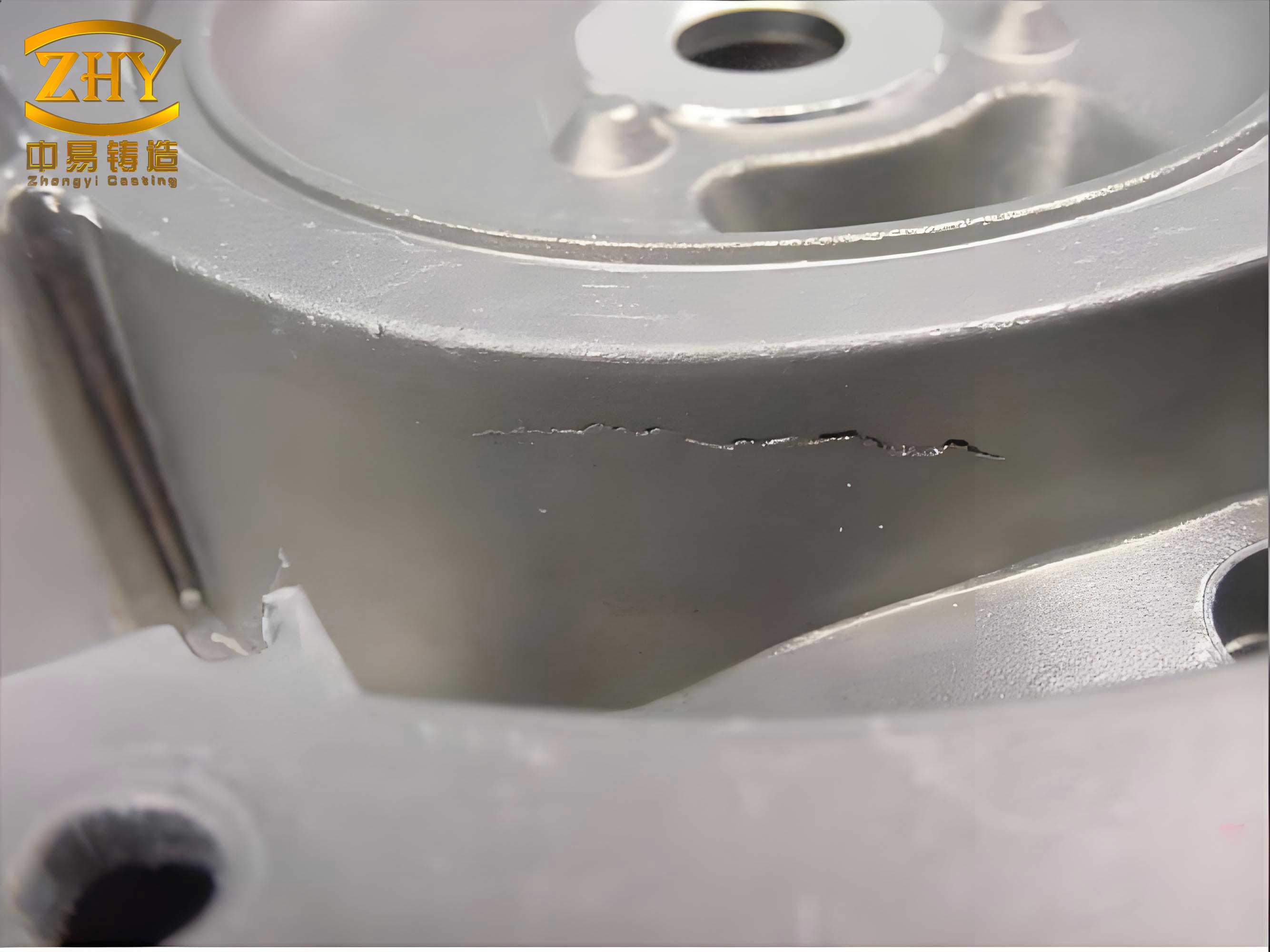
Casting defects in lost foam casting often stem from process parameter mismatches, material inconsistencies, or operational errors. I will delve into three primary defects: carbon defects, cold shuts, and slag inclusions, each with distinct causes and remedies. To quantify these issues, I will incorporate formulas and tables for clarity. For instance, the relationship between vacuum pressure and gas evolution can be modeled using the ideal gas law: $$PV = nRT$$ where \(P\) is pressure, \(V\) is volume, \(n\) is the number of moles, \(R\) is the gas constant, and \(T\) is temperature. This helps explain how insufficient vacuum leads to residual carbon, a key factor in carbon defects.
Carbon Defects: Causes and Solutions
Carbon defects are prevalent in lost foam casting, characterized by residual combustion products from the foam pattern embedding into the casting. These casting defects primarily arise from inadequate vacuum pressure, poor coating permeability, excessive foam density, or high carbon content in the molten metal. Below, I detail each cause with corresponding solutions.
1.1 Inadequate Vacuum Pressure: A low vacuum system fails to evacuate gases promptly, allowing carbonaceous residues to form. The vacuum pressure \(P_v\) should meet a critical threshold, often derived from empirical data. For example, the required vacuum can be expressed as: $$P_v \geq P_0 – \Delta P$$ where \(P_0\) is the atmospheric pressure and \(\Delta P\) is the pressure drop due to gas generation. Common sub-issues include:
- Leaky sandboxes: Audible leaks indicate air ingress, reducing vacuum efficiency.
- Blocked filters: Foreign objects restrict airflow, lowering vacuum levels.
- Clogged mesh screens: Sand particles seal screens, impeding gas extraction.
- Leaky pipes or valves: System integrity breaches cause pressure loss.
- Insufficient pipe cross-section: Undersized ducts limit flow rates.
- Inadequate循环水 in vacuum pumps: Low water levels compromise sealing.
- Misaligned automatic vacuum connectors: Poor alignment leads to leaks.
Solutions involve repairing leaks, cleaning filters, replacing screens, redesigning pipes, maintaining water levels, and aligning connectors. I recommend regular system checks to prevent these casting defects.
1.2 Poor Coating Permeability: Coatings with low gas permeability trap gases, contributing to carbon defects. The permeability coefficient \(k\) can be modeled using Darcy’s law: $$Q = \frac{kA \Delta P}{\mu L}$$ where \(Q\) is gas flow rate, \(A\) is area, \(\Delta P\) is pressure difference, \(\mu\) is viscosity, and \(L\) is thickness. Improving coating formulation enhances permeability, reducing defect risks.
1.3 Excessive Foam Density: Overly fine foam particles increase density, hindering gas escape. Foam density \(\rho_f\) should be optimized; a common range is 20–25 kg/m³. The relationship between particle size and density is: $$\rho_f \propto \frac{1}{d^3}$$ where \(d\) is particle diameter. Using larger particles or controlling pre-foaming density mitigates this issue.
1.4 High Carbon Content in Molten Metal: Elevated carbon levels promote carbonaceous residues. Adjusting charge materials or using inoculants can lower carbon content. The carbon equivalent \(CE\) can be calculated as: $$CE = C + \frac{Si + P}{3}$$ where \(C\), \(Si\), and \(P\) are weight percentages. Maintaining \(CE\) below 4.3% for cast iron helps minimize casting defects.
| Cause | Description | Solution |
|---|---|---|
| Low Vacuum Pressure | Insufficient gas evacuation due to system flaws | Repair leaks, clean filters, optimize pipe design |
| Poor Coating Permeability | Coating traps gases, increasing residue retention | Reformulate coating for higher permeability |
| High Foam Density | Fine particles impede gas escape | Use larger foam particles or control density |
| High Metal Carbon Content | Excess carbon leads to residual combustion products | Adjust alloy composition or use decarburization |
Cold Shut Defects: Causes and Solutions
Cold shuts occur when molten metal streams fail to fuse, resulting in cracks or oxide inclusions upon fracturing. These casting defects are often due to low pouring temperature, flawed gating design, or improper pouring techniques. I analyze each factor below.
2.1 Low Pouring Temperature: Insufficient superheat causes premature solidification. The pouring temperature \(T_p\) should exceed the liquidus temperature \(T_l\) by a margin \(\Delta T\), typically 50–100°C: $$T_p \geq T_l + \Delta T$$ Maintaining \(T_p\) above 1350°C for cast iron ensures proper fluidity, reducing cold shuts.
2.2 Defective Gating System Design: Improper runner or ingate placement elongates flow paths, leading to heat loss. The Chvorinov’s rule estimates solidification time \(t\): $$t = k \left( \frac{V}{A} \right)^2$$ where \(k\) is a constant, \(V\) is volume, and \(A\) is surface area. Optimizing gating to minimize \(t\) and adding risers enhance metal flow, preventing casting defects.
2.3 Inadequate Pouring Operations: Operational errors exacerbate cooling. Key issues include:
– Slow pouring speed: Low velocity increases heat dissipation. The flow rate \(Q_m\) should satisfy: $$Q_m = \rho v A$$ where \(\rho\) is density, \(v\) is velocity, and \(A\) is cross-sectional area. Accelerating pouring speed within quality limits improves fusion.
– Back-splashing or反喷: Gas generation disrupts flow, causing turbulence. Enhancing coating permeability and extending pattern drying time mitigate this.
– Interrupted pouring: Discontinuous flow prevents stream fusion. Avoiding interruptions is crucial.
| Cause | Description | Solution |
|---|---|---|
| Low Pouring Temperature | Insufficient metal fluidity due to inadequate superheat | Increase pouring temperature above liquidus point |
| Poor Gating Design | Long flow paths cause excessive cooling | Redesign gating system, add risers for thermal control |
| Improper Pouring Technique | Slow speed, back-splashing, or interruptions hinder fusion | Speed up pouring, improve coating, ensure continuous flow |
Slag Inclusion Defects: Causes and Solutions
Slag inclusions encompass炉渣, cover flux slag, and coating slag, embedding as irregular pores in castings. These casting defects originate from slag entrapment during melting, pouring, or coating failure. I detail each source and remedies.
3.1 Furnace Slag: This includes metal oxides, refractory materials, and charge slag. Oxidic slag appears black, while charge slag is white. Efficient slag removal using raking or fluxes is essential. The slag volume \(V_s\) can be estimated as: $$V_s = \frac{m_s}{\rho_s}$$ where \(m_s\) is slag mass and \(\rho_s\) is density. Minimizing \(V_s\) through proper furnace practices reduces defects.
3.2 Cover Flux Slag: Pearlite-based expanders float on metal surfaces, entering the mold as white spherical inclusions. Solutions involve using slag dams, ladle liners, or air blowing to remove slag before pouring.
3.3 Coating Slag: Coating detachment due to mold collapse or poor adhesion introduces slag. Ensuring vacuum integrity and robust pattern assembly prevents this. For instance, the adhesive strength \(\sigma_a\) should exceed the hydrodynamic force \(F_h\): $$\sigma_a > F_h = \rho v^2 A$$ where \(v\) is metal velocity. Strengthening adhesive bonds mitigates coating slag.
| Cause | Description | Solution |
|---|---|---|
| Furnace Slag | Oxides or refractory materials entrained in metal | Use efficient slag removers, optimize melting practice |
| Cover Flux Slag | Expanded flux particles carried into mold | Employ slag dams, ladle treatments, or filtration |
| Coating Slag | Coating debris from mold failure or poor adhesion | Maintain vacuum, improve coating application, secure patterns |
Inertia Friction Welding: A Contrasting Process
While discussing casting defects, it is insightful to consider inertia friction welding (IFW), a solid-state joining technique invented by Caterpillar in the 1960s. IFW involves rotating one workpiece against another under pressure, generating frictional heat to achieve plastic deformation without melting. This process avoids common casting defects like porosity, making it valuable for轴对称零件. The IFW process comprises four steps: flywheel acceleration, contact and friction heating, forging, and rotation stop. The kinetic energy \(E_k\) stored in the flywheel is: $$E_k = \frac{1}{2} I \omega^2$$ where \(I\) is moment of inertia and \(\omega\) is angular velocity. This energy dictates heat generation, with the frictional power \(P_f\) given by: $$P_f = \mu F_n r \omega$$ where \(\mu\) is friction coefficient, \(F_n\) is normal force, and \(r\) is radius. IFW’s advantages include short cycle times, excellent mechanical properties, and applicability to diverse metals, reducing焊接难度 for dissimilar materials. Unlike lost foam casting, where casting defects arise from gaseous or thermal issues, IFW’s solid-state nature minimizes such flaws, though it requires precise control of inertia and force parameters.
Integrated Prevention Strategies for Casting Defects
Based on my analysis, preventing casting defects in lost foam casting hinges on optimizing multiple parameters. I propose a holistic approach summarized in the table below, integrating vacuum, material, and operational factors. Additionally, adopting statistical process control (SPC) can monitor defect rates. For example, using a control chart for defect frequency \(f_d\): $$f_d = \frac{n_d}{N}$$ where \(n_d\) is defect count and \(N\) is total castings. Maintaining \(f_d\) within control limits ensures consistent quality.
| Defect Type | Key Parameters | Optimal Range | Monitoring Method |
|---|---|---|---|
| Carbon Defects | Vacuum pressure, coating permeability, foam density, carbon content | \(P_v \leq 0.05\ \text{MPa}\), \(k \geq 10^{-12}\ \text{m}^2\), \(\rho_f \leq 25\ \text{kg/m}^3\), \(CE \leq 4.3\%\) | Regular vacuum checks, coating tests, density measurements |
| Cold Shuts | Pouring temperature, pouring speed, gating design | \(T_p \geq T_l + 50^\circ\text{C}\), \(v \geq 0.5\ \text{m/s}\), optimized runner layout | Thermocouples, flow meters, simulation software |
| Slag Inclusions | Slag removal efficiency, coating adhesion, vacuum stability | Slag volume reduction, \(\sigma_a > 10\ \text{MPa}\), stable \(P_v\) | Visual inspection, adhesive tests, vacuum gauges |
Furthermore, implementing advanced techniques like real-time sensors for temperature and pressure can proactively address casting defects. For instance, embedding thermocouples in molds allows tracking of cooling curves, while pressure transducers monitor vacuum consistency. The integration of these data with machine learning models can predict defect occurrence, enabling preemptive adjustments. In contrast, processes like inertia friction welding rely on mechanical energy management, highlighting how different manufacturing methods require tailored defect mitigation strategies.
Conclusion
In summary, casting defects in lost foam casting, such as carbon defects, cold shuts, and slag inclusions, stem from interrelated factors including insufficient vacuum, improper temperatures, and material flaws. Through detailed analysis and the application of engineering principles—exemplified by formulas like the ideal gas law and Darcy’s law—I have outlined targeted solutions. Emphasizing preventive measures, such as optimizing vacuum systems, adjusting coatings, and controlling pouring parameters, can significantly reduce defect rates. While processes like inertia friction welding offer alternative approaches with fewer熔化-related defects, lost foam casting remains vital for complex geometries, necessitating continuous improvement. By adopting integrated strategies and leveraging technological advancements, manufacturers can enhance casting quality, minimizing casting defects and boosting productivity. Future work should focus on digital twins and AI-driven process control to further mitigate these challenges.