
**Wind Turbine Hub Casting Process Design**
As global demand for renewable energy intensifies, wind power has emerged as a critical solution. Offshore wind farms, particularly in coastal regions, represent the industry’s future growth frontier. The wind turbine hub, a core rotating component operating under extreme conditions, demands exceptional reliability. This article details our first-hand research on optimizing the for 2MW–5MW hubs, addressing defects like shrinkage porosity, slag inclusions, and graphite flotation through systematic design innovations.
1. Hub Characteristics and Casting Challenges
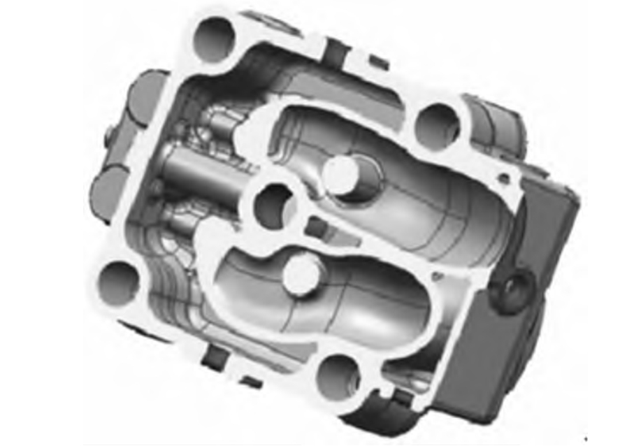
Wind turbine hubs are thick-section nodular iron castings (typically QT400-18AL/QT350-22AL), with wall thickness exceeding 200 mm in critical zones like the main shaft bore (Fig. 1). Key challenges include:
- Shrinkage Defects: Non-uniform wall thickness impedes simultaneous solidification, causing shrinkage in isolated hot spots (e.g., internal corners).
$$ \text{Shrinkage Risk} \propto \frac{\text{Section Thickness}}{\text{Cooling Rate}} $$ - Slag Inclusions: Secondary oxidation slag accumulates at upper surfaces and dead zones, appearing as dark, discontinuous streaks in magnetic particle inspection (Fig. 2).
- Graphite Degeneration: Extended solidification in heavy sections promotes coarse graphite or flotation (Fig. 3), degrading mechanical properties.
| Defect Type | Location | Root Cause | Detection Method |
|---|---|---|---|
| Shrinkage Porosity | Internal corners, thick sections | Inadequate feeding | Ultrasonic Testing |
| Slag Inclusions | Upper surfaces, blind zones | Oxidation turbulence | Magnetic Particle Inspection |
| Graphite Flotation | Core regions | High CE, slow cooling | Metallography |
2. Gating System Design Strategies
The casting process prioritizes laminar flow to minimize turbulence-induced oxidation. We contrast two approaches:
2.1 Pouring Orientation
Main Shaft Bore Upward (Fig. 4):
– Advantages: Simplifies riser placement for feeding thick sections; facilitates slag/gas buoyancy.
– Disadvantages: Risk of shrinkage at riser necks; requires precise modulus matching:
$$ M_{\text{riser}} > M_{\text{section}} > M_{\text{neck}} $$
Main Shaft Bore Downward (Fig. 5):
– Advantages: Enhances density in critical bore regions.
– Disadvantages: Slag accumulation at top surfaces; complex core support.
| Orientation | Solidification Control | Slag Risk | Application |
|---|---|---|---|
| Shaft Up | High (risers + chills) | Moderate | Hubs >4m height |
| Shaft Down | Moderate | High | Low-weight hubs |
2.2 Temperature and Velocity
For hubs >30 tons, high-temperature slow-pouring (1,350–1,370°C, 180–300s fill time) reduces slag by enhancing buoyancy. Smaller hubs use low-temperature fast-pouring (1,330–1,340°C, 100–180s) to minimize gas defects. Both require:
- Filter systems (ceramic foam) in gating
- High flow rate with low velocity (<1 m/s)
3. Feeding and Cooling Optimization
Balancing risers and chills is critical for the casting process:
3.1 Riser Design
$$ \text{Riser Efficiency} = \frac{\text{Volume Fed}}{\text{Riser Volume}} \times 100\% $$
Top Riser: Best for shaft-up orientation but creates thermal junctions. Use neck height modulation to isolate hot spots.
Side/Lip Riser: Minimizes thermal junctions but offers limited feeding range. Ideal for flange sections.
| Type | Feeding Distance | Defect Risk | Removal Ease |
|---|---|---|---|
| Top Riser | High | Neck shrinkage | Moderate |
| Lip Riser | Moderate | Top shrinkage | Easy |
3.2 Chill Application
Chills accelerate cooling in thick zones (e.g., shaft bore, pitch flange). Key principles:
- Chill modulus ≥ casting modulus at placement
- Spacing ≤ 150 mm to prevent shrinkage
Optimal chill coverage achieves directional solidification:
$$ \frac{dT}{dt}_{\text{chilled}} > \frac{dT}{dt}_{\text{unmodified}} $$
4. Metallurgical Controls
CE (Carbon Equivalent) governs graphite stability:
$$ \text{CE} = \%\text{C} + \frac{\%\text{Si}}{3} + \frac{\%\text{P}}{3} $$
Target CE = 4.3–4.5% (near eutectic) to balance shrinkage and flotation. For high-strength hubs (QT500-14), reduce Si to 1.7–2.0%.
| Grade | C (%) | Si (%) | CE (%) | Impact |
|---|---|---|---|---|
| QT400-18AL | 3.7–3.9 | 2.0–2.2 | 4.4–4.6 | Shrinkage control |
| QT500-14 | 3.6–3.8 | 1.7–2.0 | 4.2–4.4 | Strength focus |
5. Process Validation
Implementing shaft-up orientation with optimized riser/chill layouts and filtered gating reduced defects by 70% in 5MW hubs. Mechanical properties consistently met:
- UTS: 400–550 MPa
- Elongation: 14–22%
- –40°C Impact: ≥12 J
Conclusion
This casting process framework—integrating orientation strategy, turbulence-free gating, modulus-driven feeding, and CE control—ensures hub integrity under extreme operational loads. Future work will focus on thin-wall high-strength designs using QT500-14, advancing the casting process for next-generation turbines.