
In our foundry, we recently undertook the development and production of a large gearbox housing casting for a marine propulsion system. This project required meticulous attention to detail due to the stringent technical requirements and complex geometry of the component. The gearbox housing is a classic example of high-integrity ductile iron castings, which are increasingly favored in heavy-duty applications for their excellent combination of strength, ductility, and castability. The material specification was EN-GJS-400-18, equivalent to QT400-18, demanding high tensile strength, yield strength, and elongation, alongside a nodularity rate exceeding 90%. The casting’s substantial dimensions (approximately 2415 mm x 1175 mm x 1320 mm) and significant weight (3300 kg) presented challenges, particularly due to the wide variation in wall thickness, ranging from 30 mm to 152 mm. All flanges required ultrasonic testing to Grade 2 standards, and the machined part had to withstand a hydrostatic pressure test of 1 MPa for 10 minutes without leakage. Successfully producing such ductile iron castings hinges on a holistic approach encompassing metallurgical control, precise pattern and mold engineering, and rigorous process parameter management.
The structural analysis of the gearbox housing immediately highlighted the primary challenge: mitigating shrinkage porosity, shrinkage cavities, graphite flotation, and graphite degeneration in the thick sections due to slow cooling rates. These defects are common pitfalls in heavy-section ductile iron castings if the process is not carefully controlled. Furthermore, the pressure-tightness requirement added another layer of complexity, as any internal micro-porosity could lead to failure during testing. Our strategy was to design a process that promoted directional solidification where needed and ensured uniform properties throughout the casting. The following sections detail our comprehensive methodology, from melt treatment to shakeout, which enabled the successful serial production of these demanding ductile iron castings.
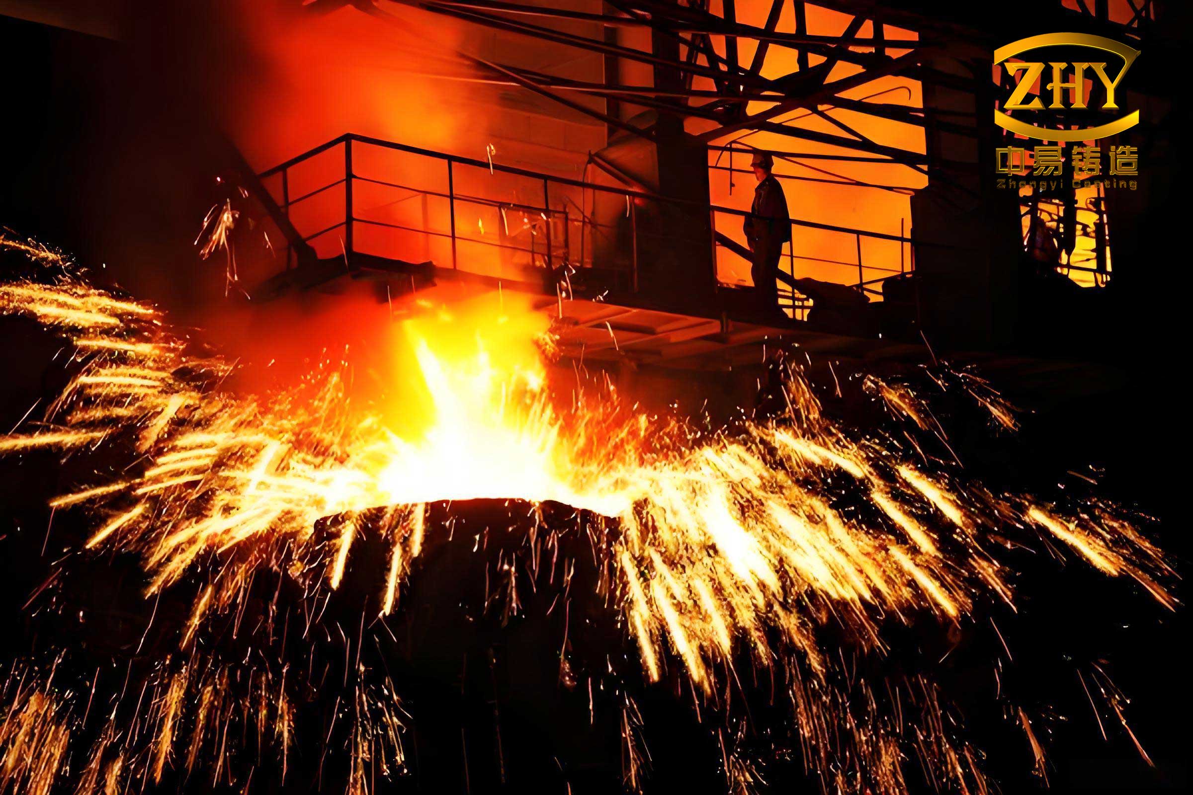
The foundation of high-quality ductile iron castings lies in precise melt preparation and treatment. We employed a medium-frequency induction furnace for melting, which provides excellent temperature control and composition homogeneity. For ferritic ductile iron grades like QT400-18, achieving the required mechanical properties in the as-cast state is paramount to avoid costly heat treatments. We established a tight chemical composition window, as summarized in Table 1. Carbon and silicon are crucial for graphitization and ferrite formation, while low levels of manganese, phosphorus, and sulfur are maintained to minimize carbide formation and segregation tendencies. The residual magnesium and rare earth (RE) contents are critical for successful nodularization and controlling trace element effects.
| Element | Target Range | Function |
|---|---|---|
| C (Carbon) | 3.6 – 3.9 | Promotes graphitization, fluidity |
| Si (Silicon) | 2.8 – 3.0 | Strong graphitizer, ferrite promoter |
| Mn (Manganese) | 0.1 – 0.3 | Minimized to prevent pearlite stabilization |
| P (Phosphorus) | ≤ 0.15 | Minimized to reduce brittleness |
| S (Sulfur) | ≤ 0.03 | Minimized to improve nodularization efficiency |
| Mgres (Residual Mg) | 0.025 – 0.050 | Essential for spherical graphite formation |
| RE (Rare Earths) | 0.03 – 0.05 | Counteracts detrimental trace elements, aids nodularization |
The melting temperature was maintained between 1500°C and 1550°C to ensure proper dissolution of alloys and adequate superheat for treatment and pouring. The nodularization process is the heart of producing ductile iron castings. We used a proprietary ferritic-grade nodularizer, with an addition rate of 1.5% to 1.6% of the total iron charge weight. The treatment was performed via the sandwich method in a preheated ladle. Inoculation is equally critical for achieving a high nodule count and preventing undercooled graphite structures like chunky or exploded graphite. We employed a dual-inoculation technique: a primary inoculation using a specialized barium-bearing ferrosilicon inoculant (3-16 mm granularity, added at 1.1%-1.2% of iron weight) in the ladle during tapping, followed by a secondary stream inoculation during mold filling. The efficiency of inoculation can be related to the fade time, and we aimed to minimize the time between treatment and pouring. The nodularity and nodule count are key metrics, often estimated using empirical relationships based on cooling rate and composition. One simplified model for the critical cooling rate to avoid carbide formation in thin sections is given by:
$$ \frac{dT}{dt}_{critical} \approx K \cdot (\%Si)^{-n} $$
where \( K \) and \( n \) are material constants, and \( \%Si \) is the silicon content. For our composition, ensuring a high silicon content helped shift the CCT diagram to favor ferrite, supporting the as-cast properties required for these ductile iron castings.
The casting process design for large, complex ductile iron castings requires a systematic approach to gating, feeding, and molding. Our first decision involved selecting the pouring position and parting plane. To facilitate core assembly, dimensional inspection of wall thickness after core setting, core venting, and overall dimensional accuracy, we chose a horizontal pouring orientation with the parting plane running through the geometric center of the casting. This split the main cavity core into two halves, simplifying manufacturing and inspection.
The mold and core system was constructed using furan no-bake resin sand. This binder system provides high strength and excellent dimensional stability, which is essential for the precision required in such ductile iron castings and allows for the consideration of riserless casting designs in certain configurations. The main cavity core (Core No. 1) was split into upper and lower halves at the parting line. Each half was designed with four core prints for precise location and robust support within the mold, preventing any movement during pouring. This design also allowed for straightforward verification of wall thickness after core assembly. Proper venting of these large cores was achieved through integrated vent channels connected to the mold exterior.
The gating system design is crucial for achieving a clean, defect-free fill. We adopted a semi-closed, bottom-gating system with multiple ingates to ensure a calm, non-turbulent fill and effective slag trapping. Turbulent flow can lead to oxide formation and dross defects, which are particularly detrimental to the pressure-tightness of ductile iron castings. The system was designed as a pressurized system to promote a faster fill of the mold cavity before the gating channels freeze. The total cross-sectional area of the ingates was determined using established empirical methods and flow calculations. We implemented eight thin, wide ingates (65 mm x 10 mm each) distributed around the casting perimeter to avoid localized overheating from the impinging metal stream. The cross-sectional area ratios were set as follows: Total Sprue Area : Total Runner Area : Total Ingate Area = 1.2 : 1.4 : 1. The sprue diameter was 90 mm. The design principles can be summarized using the continuity equation and Bernoulli’s principle for incompressible flow:
$$ Q = A_1 v_1 = A_2 v_2 $$
$$ P_1 + \frac{1}{2} \rho v_1^2 + \rho g h_1 = P_2 + \frac{1}{2} \rho v_2^2 + \rho g h_2 + \text{losses} $$
where \( Q \) is the volumetric flow rate, \( A \) is cross-sectional area, \( v \) is velocity, \( \rho \) is density, \( g \) is gravity, \( h \) is height, and \( P \) is pressure. Designing the system to be slightly pressurized helps maintain a full runner and minimizes aspiration. The calculated pouring time was targeted between 45 and 65 seconds.
Given the substantial mass and varying sections of this ductile iron casting, a feeding strategy was essential. However, the high modulus of the thick sections and the use of high-strength furan sand allowed us to employ a riserless approach based on the concept of “directional solidification towards the casting body” aided by chills. The extensive use of chills was our primary method to control solidification. Chills, made from cast iron or steel, were placed strategically on the mold faces adjacent to the heaviest sections of the casting. They act as heat sinks, extracting heat rapidly and creating a steep thermal gradient that promotes directional solidification from the chilled surface inward, thereby preventing isolated hot spots where shrinkage defects form. The chill thickness is a critical parameter; we used a rule of thumb where the chill thickness is 0.6 to 0.8 times the local casting thickness. The effectiveness of a chill can be approximated by analyzing the heat transfer at the interface. The heat extracted by a chill can be modeled as:
$$ q = h_c (T_{cast} – T_{chill}) $$
where \( q \) is the heat flux, \( h_c \) is the interfacial heat transfer coefficient, and \( T \) are temperatures. The solidification time \( t_s \) for a section can be estimated using Chvorinov’s rule:
$$ t_s = B \left( \frac{V}{A} \right)^n $$
where \( V \) is volume, \( A \) is cooling surface area, \( B \) is a mold constant, and \( n \) is an exponent (typically ~2). Chills effectively increase the cooling surface area \( A \) for the volume they contact, drastically reducing \( t_s \) and aligning it with thinner sections. Only small venting risers were placed at the highest points of the flanges and the casting top to allow for the escape of air and gases generated during mold filling.
Other essential casting process parameters for these ductile iron castings included pattern allowances. A linear shrinkage allowance of 1% was applied to all pattern dimensions. To compensate for potential dimensional shifts due to mold wall movement or machining variations, a machining allowance of 4 mm was added on the back faces of all flanges (a process allowance). A negative draft of 1 mm was applied to the parting plane to ensure proper mold closure and compensate for any sand expansion.
The pouring and post-pouring operations were tightly controlled. The treated iron was poured at a temperature range of 1370°C to 1400°C. Manual slag skimming and ignition of gases exiting the vents were performed during pouring. The controlled pour time ensured the mold filled smoothly without excessive turbulence. After pouring, the solidification and cooling process was managed. The mold clamping bolts were loosened approximately one hour after pouring to prevent hot tearing from constrained contraction. The complete shakeout was performed after 24 hours, allowing the casting to cool sufficiently within the mold to below the eutectoid transformation temperature, minimizing stresses and ensuring dimensional stability. The entire thermal history significantly influences the final microstructure of ductile iron castings. The cooling curve through the eutectic and eutectoid ranges determines the ferrite/pearlite ratio. For QT400-18, slow cooling through the eutectoid range (approx. 700-760°C) promotes the transformation of austenite to ferrite and graphite, which is desirable.
The production trial and subsequent batch manufacturing validated our process design. All castings underwent non-destructive testing. Ultrasonic examination of the flanges consistently met the specified Grade 2 quality level, indicating no significant internal discontinuities. After machining, every housing successfully passed the 1 MPa, 10-minute hydrostatic pressure test with no leaks, confirming the pressure-tight integrity of the ductile iron castings. Metallographic analysis of samples taken from both thick and thin sections confirmed a predominantly ferritic matrix with well-formed, spherical graphite nodules. The nodularity exceeded 90%, and the mechanical properties tested on separately cast coupons met the EN-GJS-400-18 specification: tensile strength > 400 MPa, yield strength > 250 MPa, and elongation > 18%. This consistency across multiple pours demonstrates the robustness of our integrated process.
| Process Stage | Parameter | Value or Specification |
|---|---|---|
| Melting & Treatment | Furnace Type | Medium Frequency Induction |
| Pouring Temperature | 1370 – 1400 °C | |
| Nodularizer Addition | 1.5 – 1.6 wt.% | |
| Inoculant Addition (Total) | 1.1 – 1.2 wt.% | |
| Residual Mg | 0.025 – 0.050% | |
| Residual RE | 0.03 – 0.05% | |
| Casting Design | Parting Plane | Horizontal, through center |
| Molding Media | Furan No-Bake Resin Sand | |
| Gating System Ratio (ΣAsprue:ΣArunner:ΣAingate) | 1.2 : 1.4 : 1 | |
| Number of Ingates | 8 (65mm x 10mm each) | |
| Feeding Strategy | Riserless, with extensive chills | |
| Chill Thickness Ratio | 0.6 – 0.8 x local wall thickness | |
| Post-Pouring | Shakeout Time | 24 hours |
| Pattern Shrinkage Allowance | 1% | |
| Machining Allowance (Flanges) | 4 mm | |
| Parting Negative Draft | 1 mm |
The successful production of these gearbox housings underscores several key principles in manufacturing large, heavy-section ductile iron castings. First, strict metallurgical control, particularly through effective nodularization and robust inoculation, is non-negotiable for achieving the required graphite morphology and matrix structure. Second, a well-designed gating system that minimizes turbulence is essential for surface quality and internal soundness. Third, for thick sections, the strategic use of chills can effectively manage solidification patterns, often eliminating the need for large, wasteful risers, which is both economically and technically beneficial. This is especially true when using high-strength molding aggregates like furan resin sand. The interplay between cooling rate and microstructure in ductile iron castings can be further explored using solidification simulation software, which models heat transfer and predicts shrinkage regions. Such software solves the Fourier heat equation:
$$ \rho c_p \frac{\partial T}{\partial t} = \nabla \cdot (k \nabla T) + \dot{q}_{latent} $$
where \( \rho \) is density, \( c_p \) is specific heat, \( k \) is thermal conductivity, \( T \) is temperature, \( t \) is time, and \( \dot{q}_{latent} \) is the latent heat release rate due to phase change. While we relied on empirical design and prototyping, simulation is a powerful tool for optimizing chill placement and gating for future, even more complex ductile iron castings.
In conclusion, the development of this marine gearbox housing demonstrates a viable and repeatable process for producing high-integrity, pressure-tight, large-scale ductile iron castings. The synergy of controlled chemistry, advanced melt treatment, a thoughtfully engineered mold and core system incorporating chills, and disciplined pouring and cooling practices resulted in castings that consistently met all performance criteria. The knowledge gained reinforces the capability of ductile iron as a premier material for demanding structural applications and provides a framework for tackling similar challenges in the production of other heavy-section ductile iron castings. Future work may focus on further optimizing chill design using simulation and exploring the effects of minor alloying elements on the as-cast ferrite fraction to potentially enhance ductility even further.