
In my experience with foundry operations, the production of high-integrity ductile iron castings, such as planetary carriers for gear transmission systems, presents significant challenges due to the stringent requirements for lightweight design, rigidity, and freedom from shrinkage defects. This article details a comprehensive casting process developed for a bilateral-plate integral planetary carrier manufactured using a DISA vertical molding line. The focus is on leveraging advanced simulation and practical design principles to ensure quality in ductile iron casting.
The planetary carrier, a critical component in planetary gear mechanisms, serves to bear loads, transmit torque, and distribute forces. It is typically the part subjected to the highest external moments, necessitating a design that is both light and stiff. The specific casting discussed here has a maximum outer contour dimension of ϕ245 mm × 98 mm, with wall thicknesses ranging from approximately 13 mm to 22 mm. The rough casting weight is 9.8 kg, and the material is ductile iron grade QT500-7. The structure comprises two annular side plates connected by four evenly spaced struts, forming a complex spatial frame with a distance of about 60 mm between the side plates. Producing such a component as a sound ductile iron casting requires meticulous attention to feeding and solidification control.
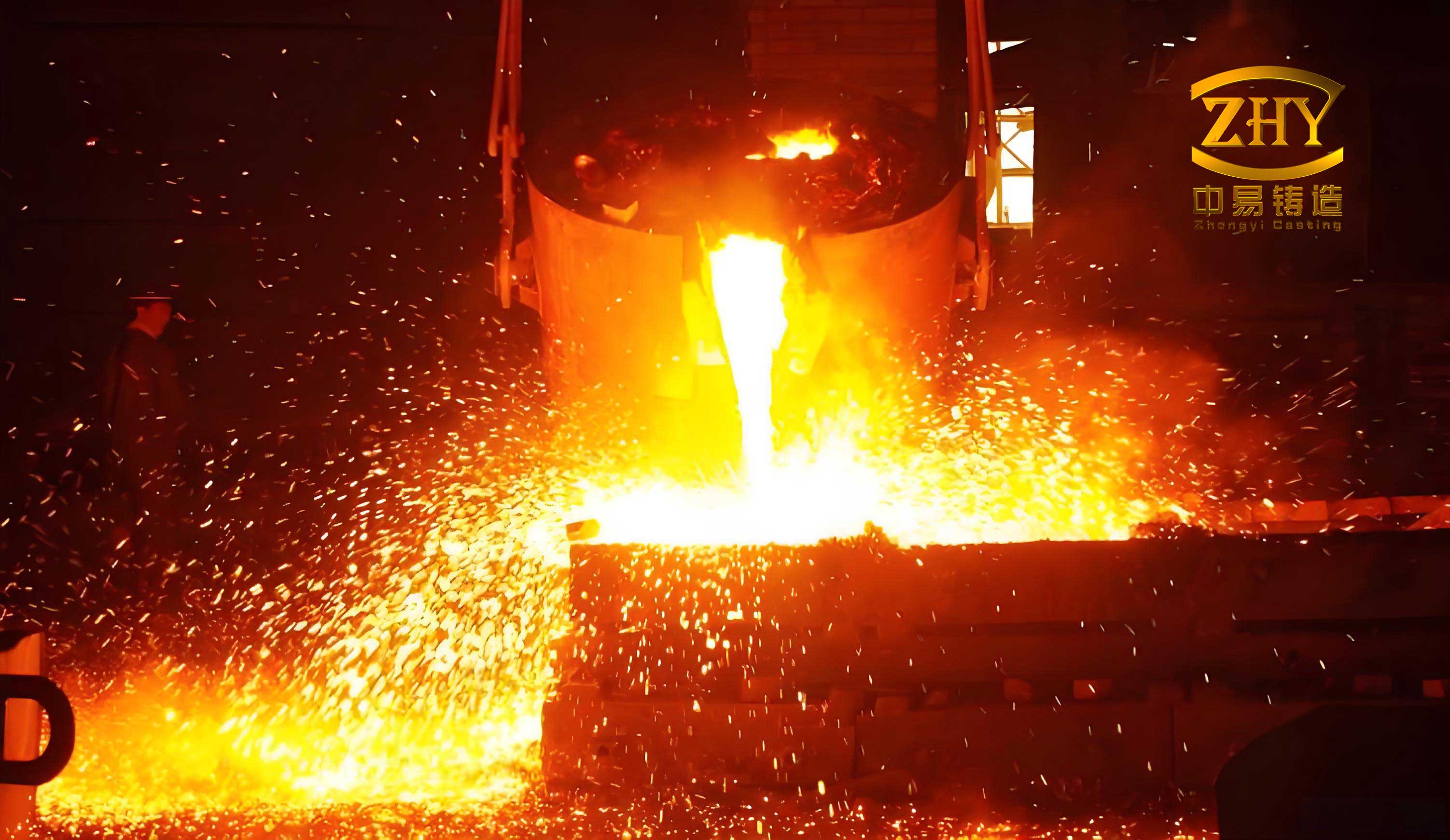
The production environment utilizes green sand molding, 20L cold-box core making, medium-frequency electric furnace melting, and DISA vertical molding line for molding. The core of the process design for any ductile iron casting lies in addressing shrinkage porosity, which begins with a thorough analysis of thermal hotspots.
Product Structure and Hot Spot Analysis
In ductile iron casting, shrinkage defects primarily arise from thermal hotspots—regions where metal accumulates, leading to prolonged solidification and potential volumetric contraction. Hotspots are categorized into structural hotspots, inherent to the component’s geometry, and process hotspots, introduced by elements like gates and risers. For this planetary carrier, the structural hotspots are concentrated at the junctions between the side plates and the struts, totaling eight locations, four on each side plate. These are critical zones requiring effective feeding strategies.
To quantify the solidification behavior, the modulus method is often employed. The modulus (M) of a section, a key parameter in feeding design, is defined as the volume (V) to cooling surface area (A) ratio:
$$ M = \frac{V}{A} $$
For the side plate-strut junctions, approximate calculations indicated a modulus around 1.2 cm. However, the differential cooling conditions between the larger and smaller side plates significantly affect their solidification patterns. The smaller side plate, having a more favorable surface area-to-volume ratio and better exposure to the mold, exhibits faster cooling. A more detailed analysis requires simulation.
We employed AnyCasting simulation software to model the solidification sequence and predict shrinkage propensity. The initial pouring temperature was set to 1385°C. The simulation revealed distinct solidification stages. The smaller side plate began to solidify and fragmented into isolated liquid pools earlier than the larger side plate. The sequential isolation of liquid sections is a critical factor in ductile iron casting, as it influences the effectiveness of both external feeding and internal graphite expansion. The predicted shrinkage probability, as shown in simulation contours, confirmed that over 30% of potential defects were located at these eight structural hotspots. This analysis guided the feeding strategy: the larger side plate hotspots, with higher moduli and longer solidification times, would require explicit riser feeding, while the smaller side plate hotspots, due to their faster cooling, could potentially be managed through controlled solidification and the self-feeding effect of graphite expansion inherent to ductile iron.
| Hotspot Location | Approximate Modulus (cm) | Solidification Sequence (from simulation) | Recommended Feeding Method |
|---|---|---|---|
| Large Side Plate & Strut Junction (4 spots) | ~1.3 | Last to solidify, forms large isolated liquid pools | External Riser Feeding |
| Small Side Plate & Strut Junction (4 spots) | ~1.1 | Solidifies earlier, forms smaller isolated pools | Controlled Cooling / Self-feeding |
Casting Process Design
The process design for this ductile iron casting was tailored to the constraints and advantages of the DISA vertical molding line, which uses a vertical parting plane and automatic core setting.
Parting Plane Selection
Two primary parting plane options were evaluated. Option 1 positioned the parting through the center of the struts, resulting in a simpler core but placing the large side plate’s hotspots far from the mold’s cope side, making riser placement inefficient. Option 2 positioned the parting at the edge of the large side plate. Although this created a more complex core with uneven machining allowances, it allowed for direct gating and riser placement adjacent to the critical hotspots on the large side plate. Furthermore, in the DISA line configuration, this orientation placed the smaller side plate towards the drag side (exterior), enhancing its cooling rate. Therefore, Option 2 was selected to optimize feeding for the most critical areas of this ductile iron casting.
Core Design
The core was designed according to DISA manual specifications for automatic setting. Locating and clamping surfaces were designed on the core prints for the positive mold plate with a controlled interference fit of -0.1 to -0.3 mm. Other clearance areas were set between 0 and 0.5 mm. The core was produced using the 20L cold-box process, ensuring good dimensional stability and surface finish for the internal cavities of the ductile iron casting.
Gating and Riser System Design
The gating system is crucial for achieving proper temperature distribution and feeding. For this ductile iron casting, the ingates were positioned between two struts on the large side plate. This strategic placement allows one riser to feed two adjacent hotspots efficiently. A key principle is to avoid directing the ingate stream directly at a hotspot, which would increase its effective modulus and worsen shrinkage.
The mold layout on the 600 mm × 480 DISA pattern plate accommodated two castings. The system featured a downsprue, a runner, and ingates. A critical design element was the use of a wide-and-thin ingate geometry (60 mm × 12 mm) to distribute metal flow gently and promote thermal gradient control. To ensure proper feeding, two cylindrical risers, each with a diameter of 70 mm, were placed to feed the four hotspots on the large side plates. A connecting bridge (30 mm × 8 mm) between the risers was designed to prevent the upper riser from feeding the lower one prematurely, thus improving the feeding efficiency of the upper riser—a vital consideration for the success of this ductile iron casting.
The feeding requirement can be related to the modulus. The riser modulus \( M_r \) should satisfy:
$$ M_r \geq 1.2 \times M_c $$
where \( M_c \) is the casting modulus at the hotspot (≈1.2 cm). Our designed riser with a diameter (D) of 70 mm and a height (H) of 100 mm has a modulus calculated for a cylindrical riser (ignoring the top surface for a top riser) as \( M_r = \frac{V}{A} = \frac{\pi (D/2)^2 H}{\pi D H + \pi (D/2)^2} \). Simplifying for a riser with a hemispherical top would yield a modulus sufficient to feed the casting hotspot.
Additional features included vent/overflow strips (18 mm × 3 mm) to reduce cavity backpressure and improve feeding, and an 82 mm × 82 mm × 12.5 mm, 10 PPI foam ceramic filter to clean and slow the metal flow. These elements collectively stabilized the process for producing this complex ductile iron casting.
| System Element | Dimensions / Specification | Function |
|---|---|---|
| Ingate (per casting) | 60 mm (width) × 12 mm (height) | Controlled metal entry, thermal distribution |
| Main Riser (cylindrical) | ϕ70 mm × 100 mm (height) | Feed metal to large side plate hotspots |
| Riser Connecting Bridge | 30 mm × 8 mm cross-section | Isolate upper riser feeding domain |
| Filter | 82×82×12.5 mm, 10 PPI foam ceramic | Metal filtration and flow rate reduction |
| Vent/Overspill | 18 mm × 3 mm strip | Pressure relief, aids feeding and prevents veining |
Solidification Simulation and CAE Analysis
The preliminary process design was modeled in 3D and analyzed using AnyCasting software. The simulation of the solidification process provided a dynamic view of the temperature fields and liquid fraction evolution. The results clearly showed that the smaller side plate solidified first, forming isolated liquid pools that shrunk rapidly. The larger side plate maintained contiguous liquid zones for a longer duration, with the risers remaining liquid longest, confirming a favorable temperature gradient for directional solidification towards the risers.
The solidification time (t) for a section can be estimated using Chvorinov’s rule:
$$ t = B \cdot \left( \frac{V}{A} \right)^n = B \cdot M^n $$
where \( B \) and \( n \) are constants dependent on mold material and metal properties. The simulation validated that the riser solidification time exceeded that of the casting hotspots, ensuring adequate feeding. The predicted shrinkage zones were predominantly confined to the risers themselves, indicating a sound casting design for this ductile iron component. The simulation provided confidence that the smaller side plate’s isolated pools, while present, might be healed by the graphite expansion pressure if the cooling rate and metallurgy were correctly controlled.
Melting and Metallurgy for Ductile Iron Casting
The quality of a ductile iron casting is fundamentally tied to its metallurgy. The iron was melted in a medium-frequency induction furnace. The base composition was adjusted to fall within the ranges specified for QT500-7, with careful control of trace elements. The nodularizing treatment was performed using a wire feeding unit, injecting magnesium-bearing wire into the molten iron. Inoculation was carried out both during the treatment and as a stream inoculation during pouring to enhance graphite nucleation and counteract chilling tendencies.
The pouring temperature was maintained between 1370°C and 1390°C to ensure adequate fluidity while minimizing shrinkage tendencies. The chemical composition of the treated iron is presented in the table below.
| Element | Target Range | Typical Achieved Value | Role in Ductile Iron Casting |
|---|---|---|---|
| Carbon (C) | 3.6 – 3.8 | 3.70 | Promotes graphite formation, fluidity |
| Silicon (Si) | 2.5 – 2.8 | 2.65 | Ferritizer, graphitizer, strengthens matrix |
| Manganese (Mn) | 0.1 – 0.4 | 0.25 | Strengthens pearlite, but can segregate |
| Phosphorus (P) | < 0.06 | 0.04 | Impurity, reduces toughness |
| Sulfur (S) | < 0.02 | 0.015 | Impurity, consumes Mg during treatment |
| Magnesium (Mg) | 0.03 – 0.05 | 0.04 | Nodularizing element, ensures spheroidal graphite |
| Tin (Sn) | 0.02 – 0.04 | 0.03 | Pearlite stabilizer, increases strength |
The success of the ductile iron casting process hinges on achieving a high nodule count and uniform matrix. The post-inoculation practice is critical for this, and its effect can be related to the undercooling during solidification. Efficient inoculation reduces the undercooling \( \Delta T \), promoting the growth of well-formed graphite spheroids.
Trial Production and Quality Verification
The process was implemented in a trial production run. The castings were poured, cleaned, and subjected to rigorous inspection. Visual examination and non-destructive testing showed no surface defects like misruns or cold shuts. The castings were then sectioned through the critical hotspot regions for macro-examination. No macroscopic shrinkage cavities or porosity were detected in the strut-to-side-plate junctions, validating the feeding design for this ductile iron casting.
Samples were taken for metallographic and mechanical testing. The microstructure exhibited a matrix of ferrite and pearlite with well-dispersed, spherical graphite nodules. The graphite nodularity exceeded 85%, with a maximum graphite nodule size of 6 µm. The pearlite content was approximately 45%, which aligns with the expected microstructure for QT500-7 grade ductile iron casting. The mechanical properties met and exceeded the specification requirements, as detailed below.
| Property | Standard Requirement (QT500-7) | Measured Result | Test Method |
|---|---|---|---|
| Tensile Strength | ≥ 500 MPa | 527 MPa | ASTM E8 |
| Elongation | ≥ 7% | 11% | ASTM E8 |
| Brinell Hardness | 170 – 230 HBW | 187 HBW | ASTM E10 |
| Graphite Nodularity | ≥ 80% (typical) | 85% | ISO 945-1 |
| Major Graphite Size | – | 6 µm | ISO 945-1 |
The correlation between microstructure and mechanical properties in ductile iron casting can be described by relationships considering the volume fractions of phases. For instance, the yield strength \( \sigma_y \) can be approximated by a rule of mixtures for the ferrite-pearlite matrix, while the graphite shape factor (sphericity) critically influences ductility. The successful results confirm the efficacy of the integrated process—from mold design to metallurgy—for producing high-performance ductile iron castings.
Discussion and Concluding Insights
The development of this casting process underscores several key principles for producing complex, sound ductile iron castings on vertical molding lines. First, a detailed structural analysis to identify and categorize thermal hotspots is indispensable. This should be complemented by modern CAE simulation tools to visualize solidification patterns and predict defect probabilities, which are invaluable for optimizing the ductile iron casting process.
Second, the choice of parting plane and pouring position is a decisive factor. It dictates the feasibility of effective feeding. Orienting the casting to place larger, slower-cooling sections near risers and smaller, faster-cooling sections in regions of enhanced chill (like the mold exterior) leverages the natural solidification gradient. This is a strategic approach in ductile iron casting to balance external feeding with the internal self-feeding from graphite expansion.
Third, the gating and risering design must be cohesive. Using risers with adequate moduli, positioning ingates to create favorable thermal gradients without exacerbating hotspots, and incorporating filters and vents are all critical subtleties. The design principle that a riser should feed multiple hotspots where possible improves yield and efficiency in ductile iron casting production.
Fourth, the metallurgical process must be tightly controlled. The combination of correct base chemistry, effective nodularization, and potent inoculation is what enables ductile iron to utilize its unique graphite expansion characteristic for self-feeding in appropriately designed sections. This intrinsic property differentiates ductile iron casting from other ferrous casting processes and must be factored into the design.
Finally, simulation results indicating isolated liquid pools, particularly in sections designed for self-feeding, should not be automatically interpreted as definitive shrinkage. In ductile iron casting, under the right conditions of cooling rate and inoculant effectiveness, the expansion pressure from the precipitation of graphite during the late stages of solidification can compensate for this contraction. However, this requires careful process control; otherwise, external aids like chills may be necessary.
In conclusion, the successful trial production of the planetary carrier validates the described integrated approach. The process delivers ductile iron castings that are dimensionally accurate, free from shrinkage defects, and possessing the required metallurgical and mechanical properties. The methodology—combining fundamental engineering analysis, advanced simulation, and robust process design—provides a reliable framework for tackling similar challenging ductile iron casting projects on high-productivity vertical molding lines. The continuous refinement of such processes is essential for meeting the evolving demands for high-integrity cast components in advanced mechanical systems.