
In the manufacturing of injection molding machines, the front plate of the shooting table is a critical component that ensures efficient injection, stable operation, and provides the required clamping force. Its performance directly impacts the quality of molded parts. This article details the casting process design for a high-hydraulic front plate made from spheroidal graphite cast iron, specifically grade QT450-10A. The focus is on overcoming technical challenges such as high machining precision, pressure resistance requirements, and the elimination of defects like shrinkage porosity. Through systematic design of gating and cooling systems, careful selection of chemical composition, and controlled melting practices, we achieved a casting that meets stringent standards. The spheroidal graphite cast iron material was chosen for its excellent mechanical properties, including good ductility and strength, which are essential for withstanding high hydraulic pressures. Below, I will elaborate on each aspect of the process from a first-person perspective, incorporating tables and formulas to summarize key points.
The front plate casting has a complex geometry with significant variations in wall thickness, ranging from 40 mm to 360 mm. The raw casting weight is approximately 1,700 kg, with a total poured weight of 1,850 kg. Key technical requirements include two oil cylinder holes that must be free from shrinkage defects, have a machined surface roughness of Ra 0.4–0.8 μm, and withstand a hydraulic pressure of 20 MPa. The material specification calls for spheroidal graphite cast iron QT450-10A, with attached test blocks requiring tensile strength ≥390 MPa, yield strength ≥260 MPa, elongation ≥8%, graphite spheroidization rate ≥85%, and graphite size of 4–7. These demands make the casting process particularly challenging, necessitating a robust design approach.
The gating system design prioritizes rapid and dispersed filling of the mold cavity to minimize turbulence, slag inclusion, and gas entrapment. For this spheroidal graphite cast iron casting, we adopted a bottom-gating system with multiple ingates on one side, characterized by a semi-open configuration. This ensures “high flow rate, low velocity, and clean, stable filling,” which helps maintain uniform temperature distribution and reduces the likelihood of shrinkage defects. The gating system consists of ceramic pipes for the sprue and ingates to prevent sand erosion, with a filter placed in the runner. The cross-sectional area ratio is set as ΣFsprue : ΣFrunner : ΣFingate = 1 : 1.25 : 1.10. The pouring time is controlled within 120–150 seconds, and the choke area is calculated using the large orifice outflow theory:
$$F_{\text{sprue}} = \frac{G}{0.31 \times \mu \times t \times \sqrt{H_p}}$$
Where \(G\) is the poured weight (1,850 kg), \(\mu\) is the flow coefficient (0.35), \(t\) is the pouring time (140 s), and \(H_p\) is the average pressure head (10.02 mm). Substituting the values:
$$F_{\text{sprue}} = \frac{1850}{0.31 \times 0.35 \times 140 \times \sqrt{10.02}} \approx 38.48 \, \text{cm}^2$$
This corresponds to one ceramic pipe with an inner diameter of 70 mm for the sprue. Based on the area ratio, the runner cross-section is 30/40 mm height by 70 mm width, and there are six ingates with inner diameters of 30 mm each. Additionally, two safety risers are placed above the oil cylinder holes to provide minimal liquid feeding during solidification shrinkage, allow gas escape, and leverage graphite expansion for densification. The overall gating system facilitates slag flotation and reduces defect probability, as summarized in Table 1.
| Component | Specification | Cross-Sectional Area (cm²) | Function |
|---|---|---|---|
| Sprue | Ceramic pipe, Φ70 mm ID | 38.48 | Controls flow rate, choke area |
| Runner | 30/40 mm × 70 mm | 48.10 (calculated) | Distributes metal, houses filter |
| Ingates | 6 × ceramic pipes, Φ30 mm ID | 42.39 (total) | Ensures平稳充型 |
| Risers | 2 safety risers | N/A | Feeding and venting |
The cooling system is critical for managing solidification and preventing shrinkage in thermal hotspots. For the four bosses on the casting, we used four chill plates sized 100 mm × 100 mm × 80 mm to accelerate cooling. However, the oil cylinder holes require exceptional integrity, so a combination of sand core and cast iron core骨架 was employed. The core consists of an outer layer of blended sand (30% chromite sand + 70% silica sand) with a thickness of 20–30 mm, wrapped around a cast iron骨架. This design promotes uniform cooling, minimizes sand drop, and avoids defects like chill whites or porosity. Simulation software was used to compare thermal profiles and defect formation between this core and a conventional sand core. The results, shown in Table 2, indicate that the composite core reduces hot spots and shrinkage defects significantly, ensuring the oil holes meet pressure requirements.
| Core Type | Hot Spot Size | Shrinkage Defect Severity | Remarks |
|---|---|---|---|
| Conventional Sand Core | Large, centered on holes | High, near risers | Prone to defects |
| Composite Core (Sand + Cast Iron Skeleton) | Small, dispersed | Low, minimal in critical areas | Enhances densification |
The chemical composition of spheroidal graphite cast iron is pivotal for achieving the desired microstructure and mechanical properties. For QT450-10A, we optimized each element based on its role in graphite formation and matrix strengthening. Carbon (C) and carbon equivalent (CE) are kept high to promote graphite precipitation and self-feeding via expansion, but within limits to avoid graphite flotation. Silicon (Si) enhances graphitization and ferrite formation, improving ductility. Manganese (Mn) is minimized to reduce segregation and pearlite stabilization, balancing strength and elongation. Phosphorus (P) and sulfur (S) are restricted as harmful impurities. The target composition is detailed in Table 3, with supporting formulas for CE and graphitization potential.
The carbon equivalent is calculated as:
$$\text{CE} = \%\text{C} + 0.33 \times \%\text{Si} + 0.33 \times \%\text{P} – 0.027 \times \%\text{Mn}$$
For our composition, CE ranges from 4.30% to 4.45%, ensuring good fluidity and graphitization. The graphitization potential \(G_p\) can be estimated as:
$$G_p = \frac{\% \text{C} + \% \text{Si}}{3 \times \% \text{Mn} + \% \text{S}}$$
This highlights the importance of low Mn and S for spheroidal graphite formation. Table 3 summarizes the compositional ranges and effects.
| Element | Target Range (wt%) | Role in Spheroidal Graphite Cast Iron | Influence on Properties |
|---|---|---|---|
| Carbon (C) | 3.45–3.65 | Promotes graphite spheroidization, increases fluidity | Higher C reduces shrinkage, improves self-feeding |
| Silicon (Si) | 2.3–2.6 | Strong graphitizer, ferrite stabilizer | Enhances ductility, solid-solution strengthens ferrite |
| Manganese (Mn) | <0.4 | Promotes pearlite, but segregates | Controlled to maintain elongation in spheroidal graphite cast iron |
| Phosphorus (P) | <0.02 | Forms brittle phosphides | Must be minimized to avoid reduced toughness |
| Sulfur (S) | <0.015 | Consumes spheroidizing agents | Low S improves Mg and RE recovery |
| Magnesium (Mg) | 0.03–0.05 (residual) | Spheroidizing element | Ensures graphite nodularity in spheroidal graphite cast iron |
| Rare Earth (RE) | 0.01–0.03 (residual) | Aids spheroidization, desulfurization | Refines graphite, improves morphology |
Melting and treatment processes are carefully controlled to achieve consistent spheroidal graphite cast iron quality. The spheroidizing agent addition is set at 1.10–1.20% to yield residual Mg of 0.03–0.05% and RE of 0.01–0.03%. Treatment involves pouring molten iron at high flow into a ladle containing the agent, which improves recovery and desulfurization. After treatment, slag is thoroughly removed, and the melt is covered with perlite to prevent re-sulfurization. Inoculation is performed multiple times to enhance graphitization and refine graphite; we use a post-inoculation technique with 0.10% inoculant added during pouring. The inoculation efficiency \(I_e\) can be expressed as:
$$I_e = \frac{\Delta N}{\Delta t} \times f_{\text{Si}}$$
Where \(\Delta N\) is the increase in graphite nodule count, \(\Delta t\) is the treatment time, and \(f_{\text{Si}}\) is the silicon factor. This ensures high nodule counts and uniform distribution in the spheroidal graphite cast iron matrix.
Pouring parameters are optimized: temperature is maintained at 1,290–1,320°C to balance fluidity and shrinkage stress, with a fast pour completed within 20 minutes after treatment to prevent fading. The pouring rate \(Q\) is given by:
$$Q = \frac{G}{t} = \frac{1850}{140} \approx 13.21 \, \text{kg/s}$$
This rapid pour minimizes temperature loss and maintains metallurgical quality.
Simulation analysis played a key role in validating the process. Using casting simulation software, we modeled solidification and predicted shrinkage porosity. The results confirmed that the composite core design reduced hot spots in the oil hole regions by approximately 30% compared to a conventional core. The Niyama criterion \(N_y\) was applied to assess shrinkage risk:
$$N_y = \frac{G}{\sqrt{T}}$$
Where \(G\) is the temperature gradient and \(T\) is the local solidification time. Values above a threshold indicate low shrinkage tendency. Our design achieved \(N_y > 1 \, \text{°C·s}^{1/2}/\text{mm}\) in critical areas, ensuring soundness. Table 4 summarizes simulation outcomes for different process variants.
| Process Variant | Maximum Hot Spot Temperature (°C) | Shrinkage Porosity Volume (cm³) | Niyama Criterion in Oil Holes |
|---|---|---|---|
| Base Design (Composite Core) | 1,150 | <5 | 1.2–1.5 |
| Alternative: Conventional Core | 1,250 | 15–20 | 0.8–1.0 |
| Alternative: No Chills | 1,300 | 25–30 | 0.6–0.8 |
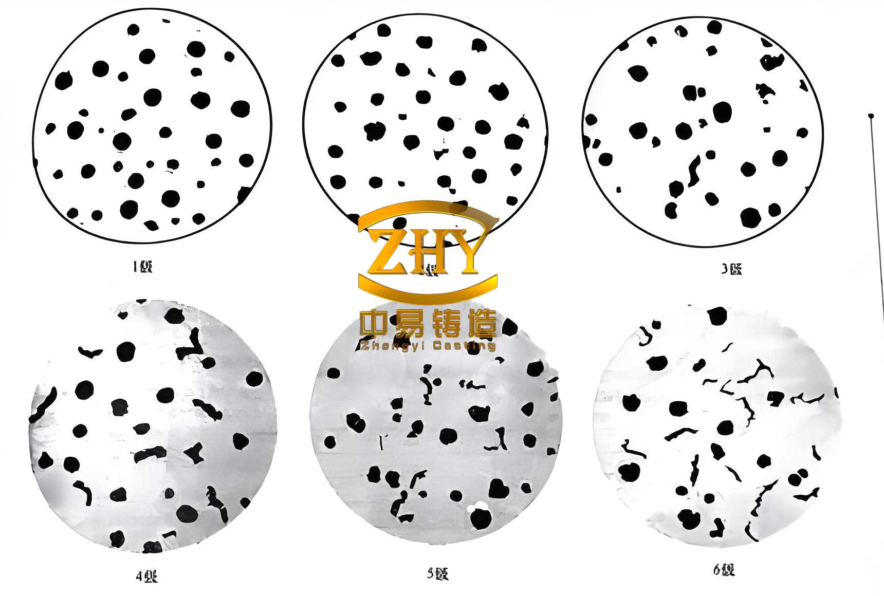
Implementation results from three trial castings demonstrated success. The castings were inspected via penetrant testing (PT) per EN 1371, achieving quality level 1 with no defects in the oil holes. Attached test blocks were evaluated for mechanical properties and microstructure. The results, shown in Table 5, meet all specifications: tensile strength ≥480 MPa, yield strength ≥340 MPa, elongation ≥11%, hardness 162 HB, graphite spheroidization rate 90%, and graphite size grade 6. The microstructure exhibited fine ferrite with well-dispersed spheroidal graphite nodules, confirming the efficacy of the process for spheroidal graphite cast iron.
| Property | Standard Requirement | Measured Value | Remarks |
|---|---|---|---|
| Tensile Strength | ≥390 MPa | 480 MPa | Exceeds standard |
| Yield Strength | ≥260 MPa | 340 MPa | Exceeds standard |
| Elongation | ≥8% | 11% | Good ductility |
| Hardness | 160–210 HB | 162 HB | Within range |
| Graphite Spheroidization Rate | ≥85% | 90% | Excellent nodularity |
| Graphite Size | 4–7 | 6 | Fine distribution |
In conclusion, the casting process for the high-hydraulic front plate in spheroidal graphite cast iron was successfully developed. Key factors include: (1) A chemical composition with C 3.45–3.65%, Si 2.3–2.6%, Mn <0.4%, P <0.02%, S <0.015%, residual Mg 0.03–0.05%, and RE 0.01–0.03% to ensure graphitization and mechanical properties. (2) A bottom-gating system with multiple ingates and safety risers, combined with chills and a composite sand-core design, to control solidification and eliminate shrinkage in critical areas. (3) The use of a composite core with chromite-silica sand and cast iron骨架 significantly enhances cooling uniformity and defect reduction, meeting the Ra 0.4–0.8 μm roughness and 20 MPa hydraulic pressure requirements. (4) Multiple inoculation and controlled pouring parameters improve graphite nodularity and casting integrity. This comprehensive approach ensures reliable production of high-quality spheroidal graphite cast iron components for demanding applications. Future work could explore optimization via machine learning algorithms to further refine process parameters for spheroidal graphite cast iron castings.
The success of this project underscores the importance of integrated design in spheroidal graphite cast iron manufacturing. By leveraging simulation, empirical formulas, and rigorous metallurgical control, we achieved a robust process that minimizes defects and maximizes performance. The spheroidal graphite cast iron material, with its unique combination of strength and ductility, proves ideal for such high-stress components. Continued advancements in cooling techniques and treatment methods will further enhance the capabilities of spheroidal graphite cast iron in industrial applications.