
In my experience as a casting engineer, the production of large-plane templates for injection molding machines presents significant challenges due to their complex geometry, stringent quality requirements, and the need for high-performance materials. This article details the comprehensive casting process design I developed for an MA-type large-plane injection molding machine template using nodular cast iron. The goal was to achieve a defect-free casting with superior mechanical properties, focusing on aspects such as mold design, gating system optimization, molten metal control, and treatment processes. Nodular cast iron, known for its excellent ductility and strength, was selected for its ability to meet the demands of heavy-duty applications. Throughout this project, I emphasized the importance of precision in every step to ensure success.
The template casting, with a material grade equivalent to QT450-10, has a rough weight of 4.8 tons and dimensions of 1,655 mm × 1,616 mm × 430 mm. Its large plane serves as the mold installation surface, requiring tight dimensional tolerances and internal soundness. The varying wall thicknesses—ranging from 40 mm to 160 mm—pose risks of shrinkage porosity, shrinkage cavities, and graphite degeneration, common issues in nodular cast iron components. To address these, I crafted a detailed casting process that balances rapid filling with controlled solidification. The use of nodular cast iron is critical here, as its graphite spheroids enhance toughness and reduce stress concentrations. Below, I outline the key elements of my design, supported by tables and formulas to summarize the data.
First, I determined the casting process scheme. Given the template’s structure, I opted for a two-box molding approach with the large plane facing upward and the parting line at this plane. This orientation minimizes distortion and facilitates machining allowances: 15 mm for the upper surface, 10 mm per side for holes, and 8 mm for the lower and lateral surfaces. The pattern was constructed from durable red pine, reinforced with a steel frame to ensure rigidity during molding. For the gating system, I applied the principle of “large flow rate, low velocity, and smooth, clean filling” to prevent turbulence and slag inclusion. A semi-closed, bottom-gating system was designed, with ingates placed along both longitudinal sides of the casting. Ceramic tubes were used for the sprue and ingates to reduce erosion. The cross-sectional area ratio is given by:
$$ \Sigma F_{\text{sprue}} : \Sigma F_{\text{runner}} : \Sigma F_{\text{ingate}} = 1 : 1.11 : 1.07 $$
where the sprue area is 81 cm², runner area 90 cm², and ingate area 86.4 cm². This ratio ensures balanced flow and minimal dross formation. Additionally, nine sand cores were incorporated, with external mold strength controlled at 0.9–1.2 MPa and core strength at 0.7–1.0 MPa to avoid excessive restraint on casting contraction. To enhance cooling on the large plane, chills were strategically placed, as shown in the layout diagram integrated later.
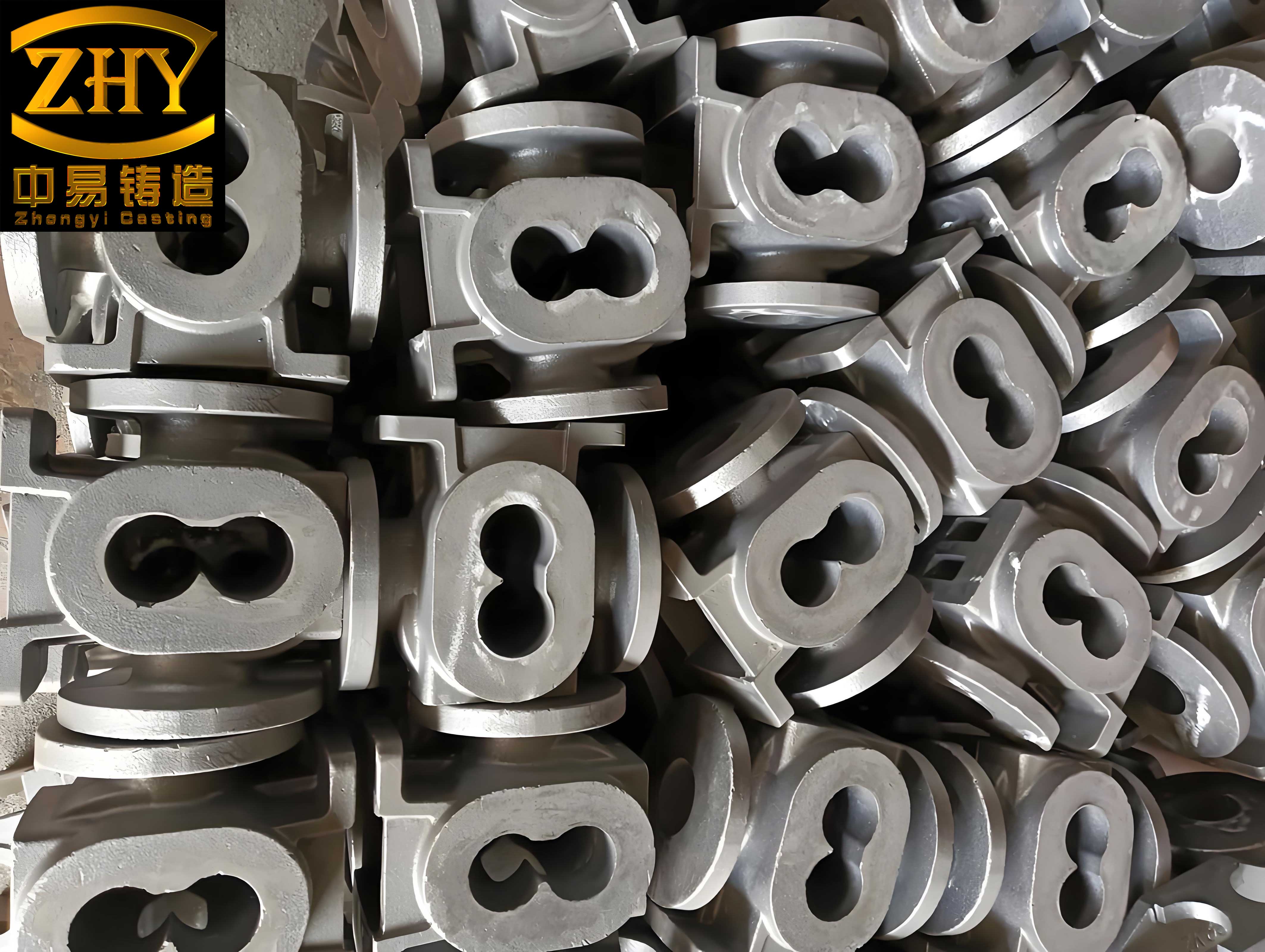
The image above illustrates the typical microstructure of nodular cast iron, highlighting the spheroidal graphite that confers its desirable properties. In this project, achieving such a structure was paramount for the template’s performance.
Next, I focused on the melting and treatment processes for nodular cast iron. The chemical composition was carefully designed to promote graphite nodulization while maintaining mechanical strength. Table 1 summarizes the target ranges, which were derived from empirical data and industry standards for nodular cast iron.
| Element | Target Range (wt.%) |
|---|---|
| C | 3.45–3.65 |
| Si | 2.3–2.5 |
| Mn | <0.6 |
| S | <0.015 |
| P | <0.02 |
| Mg | 0.03–0.05 |
| RE | 0.01–0.03 |
| Fe | Balance |
Low sulfur and phosphorus levels are essential to avoid impurities that can impair the nodular cast iron’s ductility. The magnesium and rare earth (RE) contents are critical for graphite spheroidization. To calculate the required alloy additions, I used a mass balance approach. For instance, the amount of nodulizing agent (containing Mg and RE) is determined based on the base iron’s sulfur content and desired residual magnesium. A simplified formula is:
$$ W_{\text{agent}} = \frac{(Mg_{\text{target}} + k \cdot S_{\text{initial}}) \cdot W_{\text{iron}}}{\eta_{\text{Mg}} \cdot C_{\text{Mg}}} $$
where \( W_{\text{agent}} \) is the weight of nodulizing agent, \( Mg_{\text{target}} \) is the target residual magnesium (0.03–0.05%), \( S_{\text{initial}} \) is the initial sulfur content, \( k \) is a factor accounting for sulfur neutralization (typically 0.76 for Mg), \( W_{\text{iron}} \) is the iron weight, \( \eta_{\text{Mg}} \) is the magnesium recovery rate (assumed 40–50% for the pouring method), and \( C_{\text{Mg}} \) is the magnesium concentration in the agent (6–7%). In practice, I added 1.20–1.40% nodulizing agent via the sandwich method at 1,460–1,480°C, ensuring vigorous reaction to improve recovery.
Post-nodulization, I implemented a multi-stage inoculation process to refine graphite and enhance the nodular cast iron’s properties. Inoculation additions were as follows: 0.3% primary inoculant (3–8 mm granules) atop the nodulizing agent, 0.2% trapezoidal inoculant blocks after slag removal, and 0.15% stream inoculant during pouring. The inoculant composition was primarily silicon-based with calcium and barium additives to promote nucleation. The effectiveness of inoculation can be modeled using cooling rate considerations. For example, the graphite nodule count \( N \) in nodular cast iron relates to the undercooling \( \Delta T \) and inoculation potency:
$$ N = A \cdot \exp\left(-\frac{B}{\Delta T}\right) $$
where \( A \) and \( B \) are material constants. By controlling pouring temperature at 1,330–1,350°C and limiting pouring time to under 30 minutes, I minimized temperature gradients and promoted uniform solidification of the nodular cast iron.
To validate the process, I produced several template castings and conducted thorough testing. The attached test blocks were analyzed for mechanical properties and microstructure. Table 2 presents the results, which meet all specifications for nodular cast iron.
| Property | Standard Requirement | Measured Value |
|---|---|---|
| Nodularity (%) | ≥90 | 95 |
| Graphite Size (Grade) | 4–7 | 6 |
| Tensile Strength (MPa) | ≥390 | 410 |
| Yield Strength (MPa) | ≥260 | 285 |
| Elongation (%) | ≥8.0 | 13.5 |
| Hardness (HB) | 160–210 | 165 |
The high nodularity and fine graphite size confirm the efficacy of the treatment processes for nodular cast iron. Furthermore, non-destructive testing via ultrasonic and magnetic particle inspections, according to EN 12680-3 and EN 1369 standards, revealed no defects, affirming the template’s integrity. The success of this project underscores the importance of integrated process design in manufacturing large-scale nodular cast iron components.
In refining the gating system, I also considered fluid dynamics principles. The flow rate \( Q \) through the gating channels is governed by Bernoulli’s equation, adapted for foundry applications:
$$ Q = C_d \cdot A \cdot \sqrt{2gH} $$
where \( C_d \) is the discharge coefficient (approximately 0.8 for ceramic tubes), \( A \) is the cross-sectional area, \( g \) is gravity, and \( H \) is the metallostatic head. By setting \( A \) based on the ratio above, I ensured a flow rate sufficient for fast filling without excessive velocity that could cause mold erosion. For the template casting, with a total volume \( V \) of about 0.68 m³ (estimated from weight and density of nodular cast iron, ~7,100 kg/m³), the pouring time \( t \) is:
$$ t = \frac{V}{Q} $$
With \( Q \) calculated from the sprue area and head height, I achieved \( t \approx 28 \) minutes, within the 30-minute target. This controlled pouring minimizes temperature loss and reduces oxidation in the nodular cast iron melt.
Another critical aspect was the cooling rate calculation for the thick sections. Using Fourier’s law of heat conduction, I estimated the solidification time \( t_s \) for a section of thickness \( d \) in nodular cast iron:
$$ t_s = k \cdot \left(\frac{d}{2}\right)^2 $$
where \( k \) is a constant dependent on mold material and metal properties (for sand molds and nodular cast iron, \( k \approx 0.8–1.2 \, \text{min/cm}^2 \)). For the 160 mm thick zone, \( t_s \) is approximately 25–38 minutes, justifying the use of chills to accelerate cooling and avoid shrinkage. The chill design involved placing steel plates with a surface area ratio to the casting of about 1:5, derived from empirical data for nodular cast iron.
Regarding the metallurgy of nodular cast iron, the role of magnesium cannot be overstated. The residual magnesium content \( Mg_{\text{res}} \) after treatment is a function of initial sulfur \( S_i \), added magnesium \( Mg_{\text{add}} \), and losses:
$$ Mg_{\text{res}} = Mg_{\text{add}} \cdot \eta – 0.76 \cdot S_i $$
where 0.76 is the stoichiometric factor for MgS formation. In my process, with \( S_i < 0.015\% \) and \( Mg_{\text{add}} \) from the agent, \( Mg_{\text{res}} \) consistently fell in the 0.03–0.05% range, optimal for nodule formation in nodular cast iron. Additionally, the rare earth elements helped counteract impurities like lead and bismuth, further stabilizing the graphite spheroids.
To elaborate on the inoculation effects, the secondary dendrite arm spacing (SDAS) in nodular cast iron correlates with cooling rate \( \dot{T} \):
$$ \text{SDAS} = \alpha \cdot \dot{T}^{-\beta} $$
where \( \alpha \) and \( \beta \) are constants (typically \( \alpha \approx 50 \, \mu\text{m} \cdot (\text{K/s})^\beta \), \( \beta \approx 0.3 \)). A finer SDAS enhances mechanical properties, and my controlled cooling via chills and mold design achieved a cooling rate of about 0.5–1 K/s in critical areas, resulting in SDAS around 30–40 μm for the nodular cast iron template.
In summary, the casting process for the large-plane injection molding machine template in nodular cast iron involved meticulous planning across multiple fronts. From the initial mold design to the final quality checks, every step was optimized to leverage the advantages of nodular cast iron. The tables and formulas provided here encapsulate key parameters and relationships that guided my decisions. This project not only yielded a合格 casting but also reinforced best practices for producing heavy-section nodular cast iron components. The integration of advanced gating, precise chemical control, and multi-stage treatments ensures that nodular cast iron continues to be a reliable material for demanding applications. Future work may explore computational simulations to further refine the process, but the hands-on approach described here remains foundational in foundry engineering for nodular cast iron.