
In my extensive work on developing casting processes for complex engine components, I have encountered the significant challenges posed by water-jacket exhaust manifolds. These manifolds, typically made from nodular cast iron, are critical for marine diesel engines and other applications requiring explosion-proof performance. The dual-layer structure, comprising an inner gas chamber and an outer water jacket, demands precise control over casting parameters to avoid defects such as shrinkage porosity, sand inclusion, and gas-related issues. This article details my approach to designing and implementing a robust casting process for a six-cylinder water-jacket exhaust manifold using nodular cast iron, incorporating principles of balanced solidification, advanced core-making techniques, and stringent production controls.
The manifold in question has an overall envelope dimension of approximately 1135 mm × 186 mm × 178 mm and a weight of 24.6 kg. It is manufactured from nodular cast iron grade QT400-15, which requires a ferritic matrix exceeding 90% and a nodularity rate above 80% to ensure high thermal fatigue resistance and ductility. The gas chamber walls, which handle high-temperature exhaust gases, and the water jacket walls, which facilitate coolant circulation, are both designed with a nominal thickness of 6 mm. This thin-walled, intricate geometry creates numerous isolated hot spots, making feeding and solidification control paramount. The presence of multiple cores for the gas and water cavities further complicates the process, as these cores must maintain dimensional stability, exhibit high strength to prevent breakage, and allow for efficient gas venting during pouring.
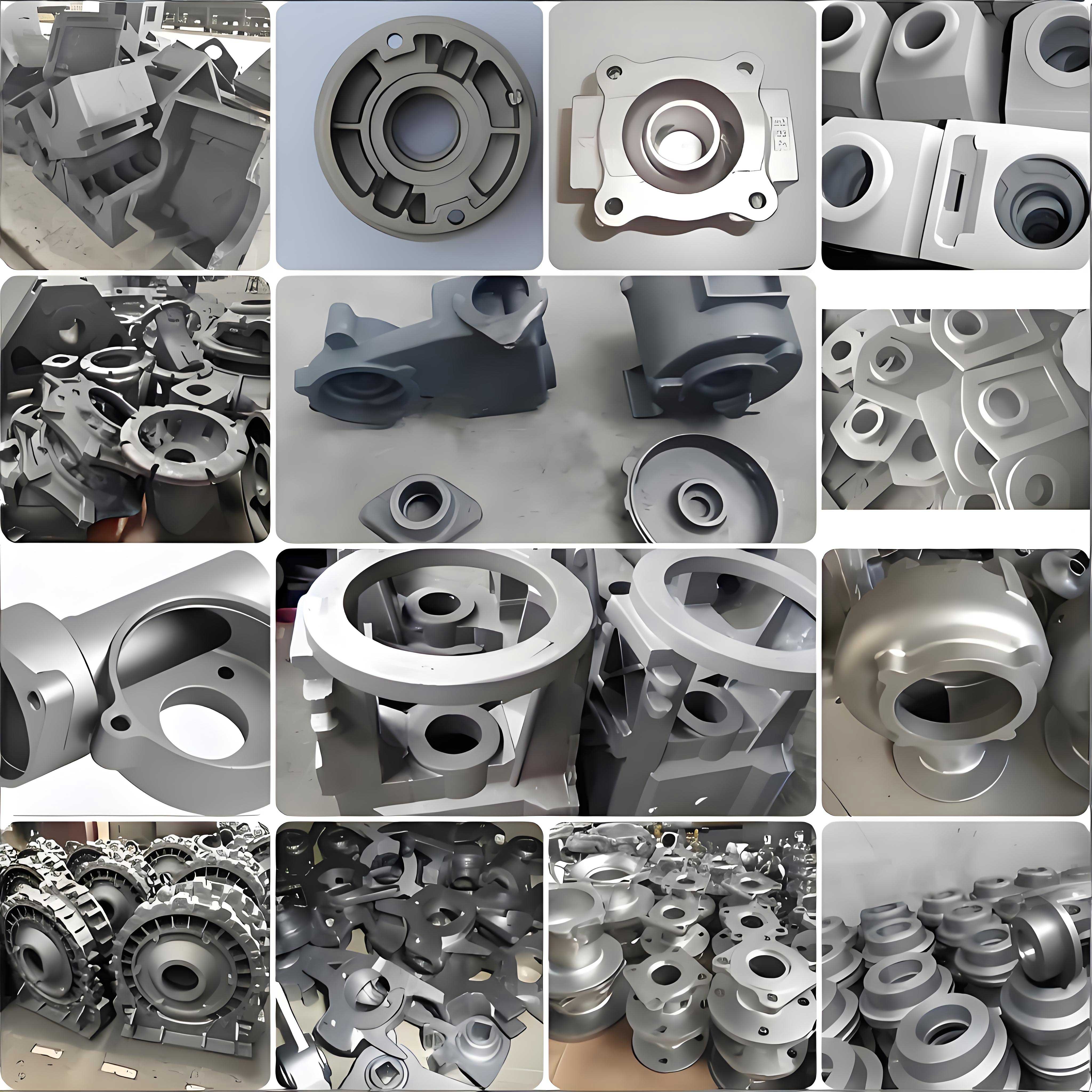
My casting philosophy for this nodular cast iron component revolves around the application of balanced solidification theory. This theory emphasizes the need to coordinate the cooling and feeding of different sections of a casting to minimize shrinkage defects without excessive use of risers. For this manifold, I employed a green sand molding process using a two-part flask, with the intake flanges oriented vertically and the parting line running horizontally through the center of the gas chamber. This orientation facilitates core placement and mold assembly. The gating and feeding system was designed using established hydraulic principles, notably the Osann formula, to determine the choke area. The gating ratio was selected as a semi-pressurized system to promote smooth filling and effective slag trapping. The relationship between the cross-sectional areas is given by:
$$ S_{\text{sprue}}:S_{\text{runner}}:\sum S_{\text{ingate}} = 1.2:1.4:1 $$
A larger runner area helps in achieving a more uniform temperature distribution and allows inclusions to float up. The ingates are designed to be short, thin, and wide to enable early closure during the graphite expansion phase, harnessing the natural self-feeding capability of nodular cast iron.
To address specific hot spots, I strategically placed side risers at locations like the intake flanges, bolt bosses, and the outlet flange. These risers are designed with “thin, wide, short, and slanted” necks to optimize feeding efficiency and terminate feeding at the right moment. The riser neck design criteria can be related to the modulus of the casting section it feeds. The modulus (M) is defined as the volume-to-surface area ratio:
$$ M = \frac{V}{A} $$
For effective feeding, the riser neck should solidify after the feeding zone but before the riser itself. In some areas difficult to feed with risers alone, I used shaped chills to locally increase the cooling rate and direct solidification. The layout of the pattern plates, including the placement of these chills, was carefully simulated to ensure a progressive solidification pattern from the thin sections towards the risers.
The core assembly is arguably the most critical aspect of this casting. The manifold requires four main cores: a lower shell core, an air chamber core, and upper and lower water jacket cores. To ensure accuracy and prevent core shift or breakage, I designed precise locating clearances, machining allowances, and parting line offsets. The typical clearance between cores and the mold or between mating cores was set between 0.3 mm and 0.5 mm, with draft angles of 3° to 5°. The water jacket cores, being long and slender, were reinforced with transverse ribs connecting the core prints at the intake flange and process hole ends, significantly enhancing their overall strength and resistance to deformation during handling and pouring.
The cores were produced using the hot-box process with a specially selected coated sand. The choice of sand is crucial for the quality of nodular cast iron castings with complex cores. I opted for a high-strength, coarse-grained (50/70 mesh) sand with low gas evolution to improve permeability and reduce the risk of gas defects. The properties of the coated sand are summarized in the table below.
| Property | Value or Range |
|---|---|
| Grain Size (mesh) | 50-70 |
| Hot Tensile Strength (MPa) | 2.2 – 2.3 |
| Room Temperature Tensile Strength (MPa) | 4.8 – 5.2 |
| Hot Bend Strength (MPa) | ≥ 2.5 |
| Room Temperature Bend Strength (MPa) | 7.0 – 8.0 |
| Gas Evolution (mL/g) | ≤ 13 |
| Loss on Ignition (%) | ≤ 3.0 |
Venting of the cores, especially the water jacket cores, was addressed by incorporating vent grooves along the parting lines of the upper and lower halves. The air chamber core was designed as a hollow structure with vent pins integrated into the core box. After making, the cores were assembled on a dedicated fixture. Adhesive was applied at the joints, and fire seals (ceramic fiber pads) were placed at the parting line of the water jacket cores to prevent the formation of fins in the internal water passage. The assembled core package was then lowered into the drag as a single unit, ensuring correct alignment and minimizing the risk of sand inclusion.
The melting and treatment of the nodular cast iron are fundamental to achieving the required microstructure and mechanical properties. I used a medium-frequency induction furnace for melting. The base iron composition was adjusted to target the final chemistry after treatment. The spheroidization treatment was performed using a sandwich method in a ladle. The treatment agent was a heavy rare-earth magnesium ferrosilicon alloy (FeSiMg7Re3), added at 1.0-1.2% of the iron weight. Inoculation was carried out in two stages: a primary inoculation of 0.3-0.5% FeSi75-C during tapping, and a post-inoculation (or stream inoculation) during pouring using a long-lasting inoculant FYJ-1a at 0.1-0.15%. The tapping temperature was maintained above 1540°C to ensure adequate fluidity and treatment effectiveness. The reaction time was controlled between 45 and 100 seconds. The chemical composition before and after treatment is shown in the following table.
| Element | Base Iron (wt.%) | Treated Iron (wt.%) |
|---|---|---|
| Carbon (C) | 3.79 | 3.61 |
| Silicon (Si) | 1.92 | 2.84 |
| Manganese (Mn) | 0.192 | 0.187 |
| Phosphorus (P) | 0.029 | 0.029 |
| Sulfur (S) | 0.011 | 0.007 |
| Rare Earth (RE) | – | 0.013 |
| Magnesium (Mg) | – | 0.038 |
The mold was produced on a jolt-squeeze molding machine using green sand bonded with bentonite and coal dust. The mold sand properties were tightly controlled to achieve the necessary strength, permeability, and moisture content. Key parameters included a permeability number above 90, a moisture content of 4.5-5.0%, and a green compressive strength of at least 0.1 MPa. To enhance venting from the mold cavity, I ensured the cope hardness was around 80 (C-scale) and drilled vent holes in all core print locations on the cope. After closing the mold, it was securely clamped with flask bars to withstand the metallostatic pressure.
Pouring parameters are critical for sound nodular cast iron castings. The pouring temperature was maintained at or above 1380°C to prevent mistruns and promote proper feeding. The entire pouring process for one mold was completed within 10 minutes, and the total time from the start of iron treatment to the completion of pouring for the last mold in a batch was kept under 15 minutes to avoid fading of the inoculation effect. A full sprue was maintained throughout the pour to minimize turbulence and air aspiration.
After shakeout, the cleaning of the water-jacket exhaust manifold presented its own set of challenges, primarily related to the removal of core sand and internal fins from the complex water passages. Initial cleaning involved standard shot blasting. For the internal water jacket, specialized techniques were employed. A boroscope was used for inspection. Internal shot blasting with small shot media was performed through the process holes, followed by vigorous air blowing to remove the media. For stubborn sand adherence or fins in死角, high-pressure water jetting proved effective. In some cases, a thermal shock method was used: heating the casting to about 600°C, holding for one hour, air cooling, and then vibrating on a shakeout grid for 10 minutes. This thermal cycling helps in cracking and dislodging the burned-on sand.
The quality of the final nodular cast iron casting was verified through metallographic examination and mechanical testing. Samples were taken from the manifold wall and from separately cast test bars. The microstructure exhibited a nodularity grade of 2 (approximately 92% nodularity) with graphite size of 7. The matrix was predominantly ferritic, exceeding 94%. The mechanical properties, as tested on attached test blocks, comfortably met the QT400-15 specification, as detailed below.
| Mechanical Property | Result |
|---|---|
| Tensile Strength (MPa) | 475 |
| Yield Strength (MPa) | 357 |
| Elongation (%) | 21 |
| Hardness (HB) | 168 |
During the initial trials, various defects such as thin walls, sand inclusions, slag, gas blows, pinholes, shrinkage, and internal fins were encountered. Each issue was systematically addressed by refining the process controls. For instance, wall thinness was mitigated by strengthening the core design and optimizing core assembly clearances. Gas-related defects were reduced by improving core venting, using low-gas sand, and controlling the coating application. The coating thickness on cores was limited to an infiltration depth of less than 1 mm to prevent excessive gas generation from the binder. Shrinkage defects were minimized by fine-tuning the riser and chill placement based on solidification simulation principles. The progressive solidification front can be modeled by considering the heat diffusion equation. The one-dimensional heat flow during solidification can be approximated by:
$$ \frac{\partial T}{\partial t} = \alpha \frac{\partial^2 T}{\partial x^2} $$
where \( T \) is temperature, \( t \) is time, \( \alpha \) is thermal diffusivity, and \( x \) is the spatial coordinate. While actual casting involves three-dimensional heat transfer, this simplified view helps in understanding the need for directional solidification.
The feeding requirement for a section of nodular cast iron is influenced by the expansion due to graphite precipitation. The net volume change \( \Delta V_{\text{net}} \) can be expressed as a function of the carbon content and cooling rate:
$$ \Delta V_{\text{net}} = \Delta V_{\text{liq-solid}} + \Delta V_{\text{graphite}} $$
where \( \Delta V_{\text{liq-solid}} \) is the contraction from liquid to austenite and \( \Delta V_{\text{graphite}} \) is the expansion from graphite formation. Successful feeding in nodular cast iron leverages this expansion to compensate for shrinkage in other areas, which is the cornerstone of balanced solidification design.
Through rigorous implementation of these tailored processes, the production yield for the nodular cast iron water-jacket exhaust manifold stabilized above 90%. The castings passed all dimensional inspections, pressure tests, and performance validation required by the engine manufacturer, confirming their suitability for service. The successful production of this component underscores the importance of a holistic approach to casting nodular cast iron, where material science, process engineering, and meticulous attention to detail converge. The use of high-quality nodular cast iron, combined with advanced core-making technology and scientifically designed feeding systems, enables the manufacture of highly complex and reliable castings for demanding automotive and marine applications. Future work could involve further optimization through computational modeling of fluid flow and solidification to reduce trial times and enhance yield predictability for similar nodular cast iron components.