
Gas turbines are known as the “crown jewel” of the equipment manufacturing industry and are the core power equipment in the 21st century. According to their structural forms, they can be divided into heavy-duty gas turbines, light-duty gas turbines, and micro gas turbines. Due to various reasons, there is still a significant gap between China’s gas turbines and the international advanced level, and a real industry has not yet been formed. A gas turbine unit consists of a compressor, a combustion chamber, a turbine, a control system, and auxiliary systems. The compressor, combustion chamber, and gas turbine are the three main components of a gas turbine. Gas turbines are classified into E-class, F-class, and H-class based on the combustion chamber temperature, with the combustion temperature of the F-class reaching above 1200°C. Compared with traditional large-scale cast steel parts for power stations, the design structure and casting process of the F-class heavy-duty gas turbine outer casing castings are completely new manufacturing technologies. These castings have large sizes, thin walls, and complex structures. Due to the operating conditions, the internal quality and dimensional accuracy of the castings are extremely demanding, making the casting production highly difficult. This article combines the structural characteristics and quality requirements of the combustor outer casing product, conducts virtual simulation through MAGMA simulation, and studies the casting process of the combustor outer casing based on the manufacturing conditions and process control requirements. A reasonable casting process scheme is designed, and ultimately, qualified casting products are produced.
- Structure and Quality Requirements of the Outer Casing Casting
- Casting Structure
The rough-machined delivery casting product of the combustor outer casing has an outline dimension of 4140 mm × 2075 mm × 1348 mm, with a main wall thickness of 45 mm, a wall thickness tolerance requirement of 0 – + 8 mm, a maximum wall thickness of 85 mm, and a minimum wall thickness of 40 mm. The casting is divided into two semi-conical structures from the middle flange, with a square inspection window at the bottom and 12 evenly distributed circular burner holes at the top. It has a complex shape and structure, belonging to a large-scale thin-walled complex steel casting, which is prone to deformation during the production process. The structure is shown in Figure 1.
As shown in Figure 1, the combustor outer casing is divided into two castings: the upper half and the lower half. The main rotating structures of the upper and lower parts are the same, except that the positions of the bosses at the flange of the upper and lower joint surfaces are staggered, and the positions of the multiple bosses distributed on the rotating outer wall have structural differences. - Casting Quality Requirements
The combustor outer casing casting is made of GX23CrMoV12 – 1 heat-resistant steel developed on the basis of Cr12 stainless steel and adheres to the EN 10213 – 2007 “Technical Conditions for Pressure-bearing Steel Castings” standard, which is equivalent to ZG23Cr12MoV steel in GB/T 16253 – 2019 “Pressure-bearing Steel Castings”. The chemical composition and mechanical properties of the material are shown in Tables 1 and 2.
After finishing machining, the surface of the heavy-duty gas turbine combustor outer casing casting needs to be installed with a layer of high-temperature-resistant material. During the operation of the unit, the steam temperature inside the casting reaches 1400 – 1500°C. Since the casting body ultimately needs to be drilled with many small holes for installing ceramic insulation sheets, there cannot be shrinkage porosity or inclusions inside the casting. Due to the working environment of the casting, which needs to withstand high temperatures and pressures, this product has strict dimensional requirements and high internal quality requirements: the casting undergoes 100% magnetic particle testing according to EN 1369, with a quality level requirement of Grade 2; the casting undergoes 100% penetrant testing according to EN 1371, with a quality level requirement of Grade 2; the casting undergoes 100% ultrasonic testing according to EN 12680 – 2, with a quality level of Grade 2 + the allowable limit value ESR (equivalent of the straight probe) of 6 mm, and RT is performed when the UT inspection results are inconclusive.
- Casting Structure
- Design of the Outer Casing Casting Process
- Design of the Casting Feeding Scheme
According to the process design principles of steel castings, the positions of risers and chills should be reasonably determined to form a good temperature gradient in the feeding range of each riser, enabling the casting to solidify sequentially from the feeding end area towards the riser to obtain a dense and sound casting. The combustor outer casing has a large size, complex shape and structure, and the main rotating structure is a large-sized thin-walled design with an equal wall thickness of 45 mm. From the design of the part structure, the part structure itself is not conducive to casting feeding and is prone to deformation. Since almost the entire casting body needs to be drilled, the internal quality requirements of the casting are high, and there cannot be shrinkage porosity or inclusions. Its material grade is GX23CrMoV12 – 1, which belongs to a high-Cr martensitic heat-resistant steel. The flowability of the material is poor, and compared to low-alloy materials, its feeding distance is short, the feeding effect is poor, and shrinkage porosity and shrinkage holes are prone to occur during the solidification process. Therefore, in the casting process design, it is necessary to design the distribution and feeding of the risers based on the casting structure and the feeding performance of the material. The distribution of the risers should be set according to their effective feeding distance. According to the structural characteristics of the outer casing product, it is necessary to adopt segmented and zoned feeding. In each riser feeding area, it is also necessary to fully consider the feeding performance of the material, and by increasing the temperature gradient during the solidification process from the end area of each area to the riser position, the casting structure can be made dense to obtain a qualified product.
In the casting process design, based on the structure of the outer casing casting, it is divided into upper and lower sections from the bottom of the inspection window. The lower section is divided into zones according to the feeding distance to set up blind risers. The upper section is divided into zones according to the positions of the 12 circular burner holes, and open risers are set at the top for feeding. For the positions of the 12 circular burner holes in the upper section, two riser distribution schemes are designed. In Scheme 1, risers are set in two circles in the inner flange of the top surface and the outer flange of the burner hole based on the casting structure, as shown in Figure 2(a). In Scheme 2, every other burner hole is cast solid, and risers are set at the positions of the cast-solid burner holes, as shown in Figure 2(b).
Compared to Scheme 2, Scheme 1 has a larger number of risers and requires more steel water. After optimization through process calculations combined with MAGMA software solidification simulation adjustments, the riser distribution method of Scheme 2 is finally determined. The lower-layer blind risers are adjusted from spherical fiber risers to exothermic insulation risers, and the casting level of the open riser platform and the top surface flange position is optimized. After improving the feeding area, feeding gradient, and meat-increasing subsidy design of each riser, the scheme is shown in Figure 3.
The lower section of the casting process design is divided into 5 zones, each with a blind riser, and external cold partitions are used between the risers. The upper section is divided into 6 zones, and an open riser is set for every other circular burner hole. From the position of the 1:10 slope meat-increasing subsidy at the bottom of the upper and lower section partition area of the inner cavity inspection window, the temperature gradient during the solidification process of each feeding area under each open riser is improved. External cold partitions are used between each feeding area to ensure the internal density of the main area of the casting. - Design of the Molding Method
Based on the casting structure, combined with the production tooling and auxiliary equipment, molding, and pouring conditions of our factory, the method shown in Figures 4 and 5 is adopted. By adding cutting ports to the joint surface flange, the upper and lower halves of the combustor outer casing are connected and cast into a ring, which can not only improve the molding and pouring production efficiency but also effectively prevent the deformation of the casting.
The middle flange is selected as the parting surface, the main core of the inner cavity is an integral structure, and the separate core is placed at the connecting cutting port of the upper and lower joint surface flanges. The parting surface and the main core structure are shown in Figures 6 and 7. - Control of Size and Crack Risk
For the large-sized thin-walled structure of the combustor outer casing, during the casting process scheme design, not only the deformation caused by the inconsistent cooling shrinkage in different areas during the solidification process of the casting needs to be considered, but also the prevention of the deformation of the casting during the heat treatment process should be considered in combination with the loading method of the heat treatment process design. At the same time, for the problem of high hot cracking tendency of high-Cr martensitic heat-resistant steel, effective preventive measures need to be taken for the high-risk areas of hot cracking in the MAGMA stress simulation results.
Based on the production experience of similar semi-annular joint casting structure products in our factory and the wall thickness tolerance requirements of the outer casing casting, a reasonable machining allowance and blank surface correction amount are selected, and a 1.8% shrinkage scale is selected based on the analysis of the MAGMA stress simulation results. According to the heat treatment process, after the molding, shakeout, and cleaning of the outer casing casting, the upper and lower halves will be cut apart from the joint surface of the flange, and the performance heat treatment will be carried out separately. To prevent the deformation of the semi-annular structure of the casting at the opening during the heat treatment process, the casting process sets upper and lower two layers of tension ribs in the opening direction according to the requirements of the heat treatment process. According to the loading method of the casting heat treatment, to prevent the high-temperature deformation of the shell during the heat treatment process, a large triangular rib for preventing deformation is set at the inflection point of the inner cavity of the middle flange. For the four rounded corners of the inspection window, the anti-deformation tension ribs, and the middle parting surface flange position, which show a large hot cracking tendency in the simulation results, the rounded corners are all increased to R120 mm. All the partition external colds on the main wall thickness use round steel external colds to prevent the occurrence of cracks between the external colds. - Design of the Pouring System
The material of the combustor outer casing casting, GX23CrMoV12 – 1, is a high-Cr martensitic heat-resistant cast steel with poor fluidity of the molten steel and is prone to the generation of oxide inclusions. Therefore, the pouring process needs to be stable and rapid to reduce gas entrapment and slag inclusion during the pouring process. To ensure stable filling and smooth exhaust, a bottom-gated pouring system is designed in the process. To reduce the turbulence of the molten steel entering the mold cavity and improve the floating ability of the slag inclusion, a tangentially introduced bottom-gated inner nozzle is specially designed to ensure the stable and rapid filling of the molten steel after entering the mold cavity. Combined with the actual production situation, a single ladle with a diameter of 90 mm and double ladle eyes with argon gas protection pouring is adopted. The pouring system design is shown in Figure 8. - Analysis of the Solidification Simulation Results
Through multiple adjustments and optimizations of the scheme using the MAGMA software simulation, the shrinkage cavity and shrinkage porosity simulation results of the final process scheme determined are shown in Figures 9 and 10.
The simulation results show that there is no indication of shrinkage cavity defects in the casting body as a whole. According to the application experience of the MAGMA software, the niyama (shrinkage porosity) criterion is selected to be 0.3 – 0.6 for analysis of thin-walled castings. When the niyama criterion is set to 0.3, there is no defect indication in the casting body; when the niyama criterion is set to 0.6, except for the riser and tension rib positions, only some point-like defects are indicated in the local position of the external cold partition. According to the experience of using the MAGMA software, the point-like niyama indication in the external cold partition area of thin-walled castings has no quality risk.
- Design of the Casting Feeding Scheme
- Production Process Control
To ensure the quality of the castings, the model structure is reasonably divided into blocks, and the model is manufactured using numerical control machining to ensure the model dimensions. After completion, the dimensions of the model and core box are detected through three-dimensional inspection, and all dimensions are qualified, with the deviation within the tolerance range of the model dimensions. The molding uses alkaline phenolic resin sand for molding, and the surface of the mold cavity is brushed with a water-based zircon powder coating. Since the inner cavity structure of the casting is formed by the sand core, the core setting dimensions need to be strictly controlled during the molding and core setting process. During the molding process, auxiliary methods such as template inspection are used to ensure the dimensional accuracy of the casting cavity. The upper large conical surface and the upper box surface of the casting are prone to defects such as porosity and slag inclusion. Before pouring, an endoscope is used to check and remove floating sand and other debris inside the mold cavity to ensure the cleanliness of the mold cavity. - Product Quality Status
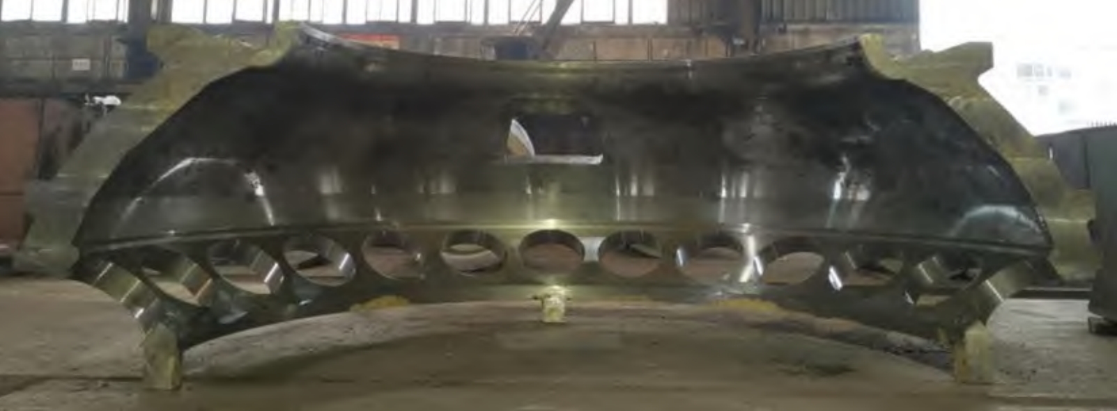
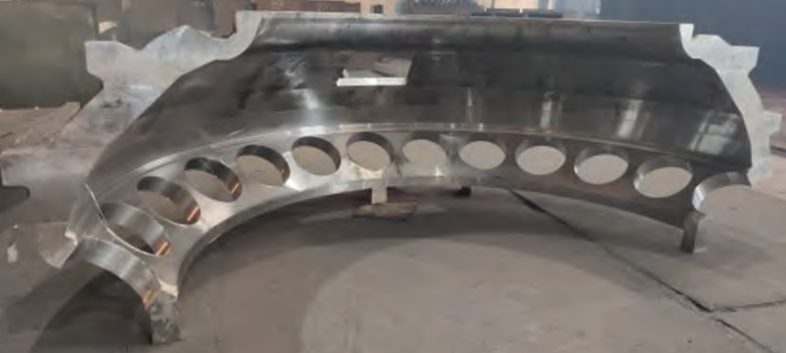
The chemical composition and mechanical properties of the combustor outer casing casting meet all the indicators required in Tables 1 and 2. The surface quality of the casting after shakeout is good, and no visual surface defects such as slag inclusion, porosity, cold shut, or cracks are found. The dimensional deformation of the product during the marking in the processing workshop is consistent with the simulation results, and there is no problem of dimensional deficiency. The machined surface of the casting after rough machining meets the requirements of the rough machining process allowance, and the photos of the product after rough machining are shown in Figures 11 and 12.
The dimensions of the casting are detected through three-dimensional data, and the comparison of the three-dimensional detection data after rough machining with the part numerical model dimensions is shown in Figures 13 and 14. All dimensions meet the design requirements.
According to the technical requirements, the casting as a whole has undergone MT, PT, and UT inspections. From the results of the nondestructive testing, the surface and internal quality of the casting meet the design requirements. - Conclusions
The casting process scheme of the combustor outer casing determined with the assistance of the MAGMA software effectively guarantees the feeding and dimensional quality of the casting and avoids the risk of cracks. Summarizing the casting process and physical quality of the combustor outer casing casting, the following conclusions are drawn:- For such castings with thin-walled and complex structures, the zoned and segmented feeding method can effectively ensure the internal quality of the casting.
- Combined with the filling simulation results, the bottom-gated and tangential pouring system effectively ensures the stable filling of the molten steel during the pouring process, avoiding the occurrence of porosity and slag inclusion defects.
- Through the MAGMA stress simulation results, the anti-deformation tension ribs and triangular ribs set for the combustor outer casing casting effectively avoid the occurrence of deformation and cracks in the casting. The shrinkage scale, correction, and machining allowance determined based on the dimensional results of the MAGMA simulation are reasonable, ensuring that the dimensions of the finished casting meet the product delivery requirements.
- The upper and lower half joint casting method of the combustor outer casing casting not only improves the production efficiency but also prevents the deformation of thin-walled annular parts.
Table 1: Chemical Composition Requirements (mass fraction, %)
| Element | Content (%) |
|---|---|
| C | 0.26 |
| Mn | 0.40 – 0.80 |
| Si | 0.30 – 1.30 |
| Cr | 11.00 – 12.50 |
| Mo | 0.80 – 1.20 |
| V | 0.20 – 0.30 |
| Cu | ≤0.30 |
| Al | ≤0.35 |
| Ti | ≤0.25 |
| Sn | Report for reference |
Table 2: Mechanical Performance Requirements
| Test Temperature (°C) | R_o.2 (MPa) | R (MPa) | A (%) | KV2 (J) |
|---|---|---|---|---|
| 20 | ≥540 | 740 – 880 | ≥15 | ≥27 |
| 550 | ≥290 | Report for reference |
In conclusion, the casting process research of the F-class gas turbine combustor outer casing is of great significance for improving the quality and performance of gas turbine castings. By optimizing the casting process design and implementing effective production process control, we can ensure the production of high-quality combustor outer casing castings, which will contribute to the development of the gas turbine industry. Further research and innovation in this field are still needed to meet the increasingly demanding requirements of the market and technology.