
In my experience working with ductile iron components, particularly in heavy machinery and engine blocks, addressing casting defects is a critical aspect of manufacturing and maintenance. Casting defects such as porosity, cracks, shrinkage cavities, and inclusions can compromise structural integrity, leading to failures if not properly repaired. Traditional hot welding methods, while effective, involve high-temperature preheating, which increases labor intensity, production costs, and poses safety risks. Moreover, they are unsuitable for post-machining repairs. Therefore, I have focused on developing and refining cold welding techniques that eliminate the need for extensive preheating, thereby enhancing efficiency, reducing costs, and improving working conditions. This article delves into a detailed cold welding methodology for significant casting defects in ductile iron, combining nickel-based electrodes for root passes with mixed gas shielded welding for fill layers. Throughout this discussion, I will emphasize the importance of identifying and mitigating casting defects, using tables and formulas to summarize key parameters and principles.
Casting defects in ductile iron arise from various factors during the solidification process, including improper gating design, alloy composition fluctuations, and cooling rate variations. These defects can be categorized into surface defects like scabs and internal defects such as microporosity. Specifically, in ductile iron, which is characterized by its spherical graphite nodules, defects often manifest as gas porosity due to trapped gases or cracks from thermal stresses. The presence of these casting defects not only affects mechanical properties but also necessitates reliable repair methods to salvage expensive components. In my practice, I have observed that defects exceeding certain dimensions require a systematic approach to ensure weld quality and component performance. The cold welding method I describe here is tailored for such scenarios, particularly for defects identified before precision machining.
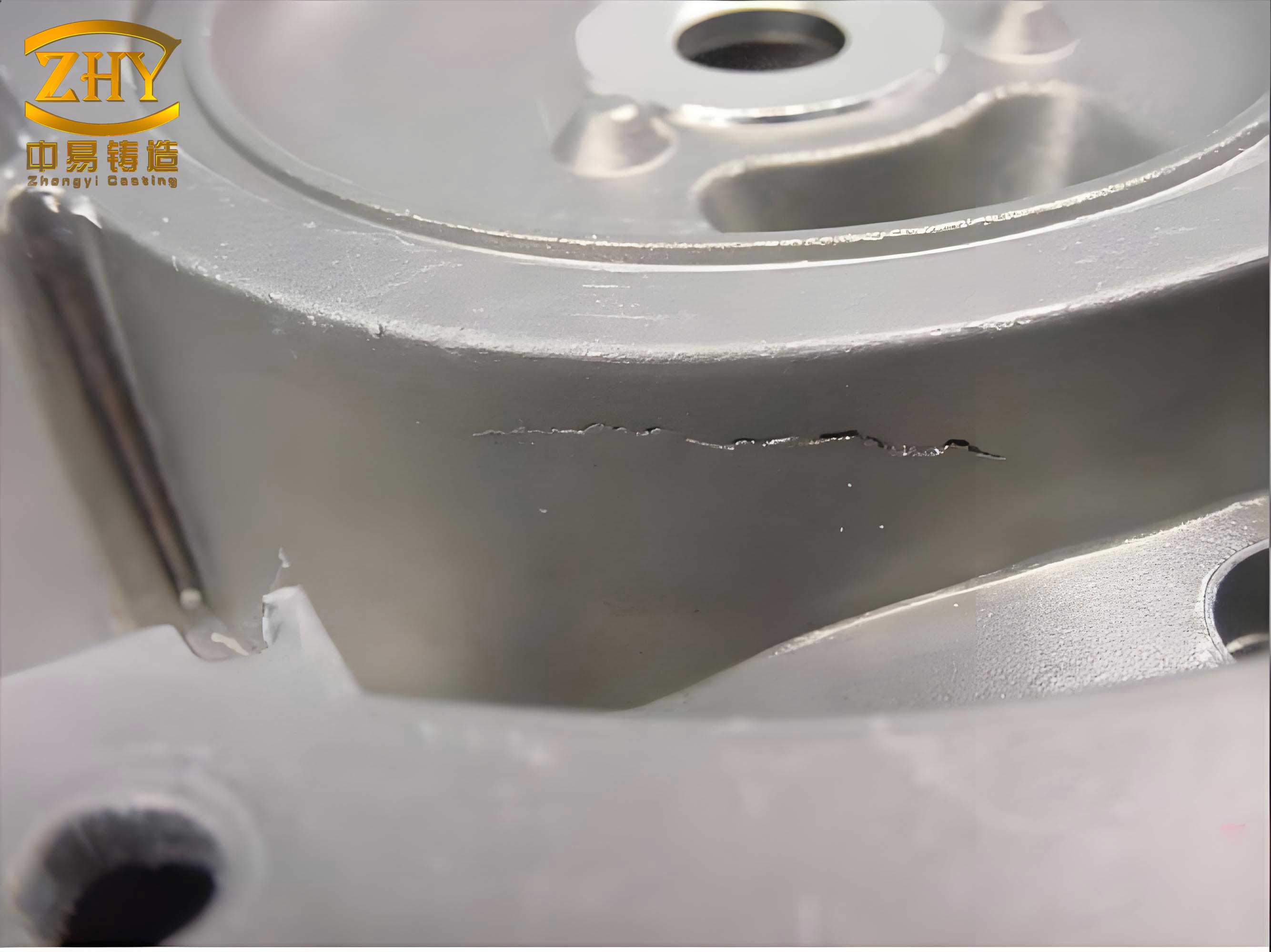
The need for cold welding stems from the limitations of conventional repair techniques. Hot welding, while providing good fusion and minimizing white cast iron formation, requires preheating the entire component to temperatures around 600°C to 700°C. This process is energy-intensive, time-consuming, and can induce distortions, especially in large castings. In contrast, cold welding operates at or near ambient temperatures, significantly reducing thermal stresses and the risk of further cracking. Based on my trials, I found that using nickel-based electrodes for the initial layer leverages the nickel-iron infinite mutual solubility principle, which minimizes carbide formation and ensures a ductile transition zone. The subsequent use of mixed gas shielded welding with argon-carbon dioxide mixtures enhances deposition rates and control, making it ideal for filling larger volumes efficiently. This hybrid approach balances cost and performance, addressing casting defects effectively without compromising on quality.
Before proceeding with welding, a thorough inspection of casting defects is paramount. Cracks, in particular, can propagate if not entirely removed, leading to weld failures. I employ several non-destructive methods to detect and delineate defects. First, visual examination with a 5x to 10x magnifying glass helps identify crack initiation and termination points. For subtle cracks, I apply localized heating to approximately 200°C using an oxy-acetylene flame; the thermal expansion and contraction make faint cracks visible. Additionally, the penetrant method involving kerosene is effective: after applying kerosene to the suspected area, I wipe the surface and dust it with talcum powder, then lightly tap with a hammer to reveal crack traces through oil seepage. These steps ensure that all casting defects are accurately mapped for precise repair, reducing the likelihood of遗漏 defects during welding.
Preparation of the casting prior to welding is crucial for successful repair. I always begin with stress relief annealing of the ductile iron component, regardless of the welding method. This involves heating the casting to a temperature between 500°C and 600°C, holding for a sufficient time based on thickness, and slowly cooling to relieve residual stresses from casting and machining. The annealing process can be described by the following formula for stress relaxation: $$\sigma(t) = \sigma_0 e^{-kt}$$ where $\sigma(t)$ is the stress at time $t$, $\sigma_0$ is the initial stress, and $k$ is a material-dependent constant. This step minimizes the risk of cracking during welding. Next, I prepare the defect area by machining a groove. For porosity or inclusions, I use U-shaped or V-shaped grooves with dimensions encompassing the entire defect, as shown in Table 1. For cracks, I drill stop-holes at both ends with diameters ranging from 3 mm to 8 mm, then widen the top into a喇叭 shape and create a 60° V-groove or X-groove for through-thickness cracks. All machining is done cold via grinding or milling to avoid heat-induced damage.
| Defect Type | Groove Shape | Depth (mm) | Width (mm) | Included Angle |
|---|---|---|---|---|
| Porosity | U-shaped | 10-20 | 8-15 | N/A |
| Cracks | V-shaped | Based on crack depth | 5-10 | 60° |
| Shrinkage | X-shaped | Full thickness | 10-20 | 60° per side |
After grooving, I clean the area meticulously to remove contaminants like oil, grease, or sand. This involves solvent cleaning followed by drying, or flame cleaning with an oxy-acetylene torch to burn off residues. The cleaning zone extends 20 mm on either side of the groove to ensure bare metal exposure. Contaminants can introduce hydrogen embrittlement or porosity in the weld, exacerbating casting defects. The cleanliness standard can be quantified by surface energy measurements, but in practice, I rely on visual and tactile inspections to confirm a grease-free surface.
The welding methodology I adopt is a two-stage process. First, I use nickel-based electrodes such as Z308, Z408, or Z438 for the root pass. These electrodes contain high nickel content, which promotes austenite formation and reduces carbon migration, thereby minimizing white cast iron layers. The welding parameters are critical; I use small-diameter electrodes to limit heat input. Table 2 summarizes the welding parameters for these electrodes. The power source is direct current electrode positive (DCEP), which provides deep penetration and stable arcs. For the root pass, I deposit a layer at least 8 mm thick, ensuring full coverage of the defect base. The welding is performed in short segments not exceeding 50 mm in length to control heat accumulation.
| Electrode Diameter (mm) | Welding Current (A) | Preheating Temperature (°C) | Interpass Temperature (°C) | Electrode Baking (℃ for 1 hour) |
|---|---|---|---|---|
| 2.5 | 75-85 | 150 | 50 | 150 |
| 3.2 | 90-120 | 150 | 50 | 150 |
During welding, I employ intermittent welding techniques. After each segment, I immediately remove slag and peen the weld bead with a rounded hammer to relieve residual stresses. Peening induces compressive stresses that counteract tensile stresses from cooling, reducing crack susceptibility. The temperature is allowed to drop to around 50°C (warm to touch) before proceeding to the next segment. This thermal management is vital to prevent overheating, which can expand the heat-affected zone and promote undesired phase transformations. The cooling rate can be modeled using Fourier’s heat conduction equation: $$\frac{\partial T}{\partial t} = \alpha \nabla^2 T$$ where $T$ is temperature, $t$ is time, and $\alpha$ is thermal diffusivity. By controlling segment length and cooling intervals, I maintain a low thermal gradient.
Once the root pass is completed and smoothed via grinding, I proceed with mixed gas shielded welding for the filler layers. The gas mixture consists of 80% argon and 20% carbon dioxide, which provides a stable arc, good penetration, and minimal spatter. I use H08Mn2SiA焊丝 with a diameter of 1.0 mm, as it offers good ductility and strength matching with ductile iron. The welding current is set between 100 A and 120 A, with a voltage range of 18 V to 22 V. Similar to the root pass, I weld in segments up to 100 mm long, peening each layer and maintaining interpass temperatures below 50°C. The deposition sequence follows a weave pattern to ensure sidewall fusion and avoid lack-of-fusion defects, which are common in repairing casting defects.
To quantify the heat input during welding, I use the formula: $$Q = \frac{VI}{v}$$ where $Q$ is heat input (J/mm), $V$ is voltage (V), $I$ is current (A), and $v$ is travel speed (mm/s). For cold welding, I keep $Q$ below 1.5 kJ/mm to minimize dilution and distortion. Additionally, the dilution ratio $D$ between the weld metal and base metal affects microstructure; it can be estimated as: $$D = \frac{A_b}{A_w + A_b} \times 100\%$$ where $A_b$ is the cross-sectional area of melted base metal and $A_w$ is the area of added weld metal. For nickel-based root passes, $D$ is kept low (below 30%) to preserve the beneficial effects of nickel.
Pre-weld low-temperature preheating to 150°C is consistently applied. This step equilibrizes temperatures across the welding zone, reduces thermal shocks, and helps evaporate any residual moisture. I use oxy-acetylene flames for uniform heating over a 100 mm radius around the groove. Preheating also aids in reducing hydrogen diffusion, which can cause cold cracking. The relationship between preheating temperature and crack prevention can be expressed through the carbon equivalent formula for ductile iron: $$CE = C + \frac{Si}{4} + \frac{Mn}{6} + \frac{Ni}{15} + \frac{Cr}{5}$$ where CE is carbon equivalent, and elements are in weight percent. For ductile iron with CE around 4.3%, preheating to 150°C significantly lowers the risk of hydrogen-induced cracking.
Throughout the welding process, several precautions are essential. I always bake electrodes as per Table 2 to remove moisture, which is a source of hydrogen. The welding environment must be dry, clean, and well-lit, with ambient temperatures above 15°C to prevent condensation. Drafty areas are avoided to shield the gas coverage. Equipment calibration is regular to ensure stable parameters. I document each step, including preheat temperatures, welding times, and any anomalies, for quality tracking. Inspection teams verify welder qualifications and monitor procedure adherence.
Post-weld heat treatment may be necessary depending on application requirements. For critical components, I recommend stress relief annealing at 550°C to 600°C for one hour per inch of thickness, followed by furnace cooling. This step further reduces residual stresses and enhances toughness. The effectiveness of post-weld heat treatment can be assessed through hardness tests; I aim for a hardness below 210 HB in the weld zone to ensure machinability. The kinetics of stress relief can be described by the Arrhenius equation: $$k = A e^{-E_a/RT}$$ where $k$ is the rate constant, $A$ is the pre-exponential factor, $E_a$ is activation energy, $R$ is the gas constant, and $T$ is temperature. This helps in optimizing treatment durations.
In conclusion, the cold welding method combining nickel-based electrodes and mixed gas shielded welding is highly effective for repairing significant casting defects in ductile iron. This approach addresses key challenges such as white cast iron formation, cracking, and cost efficiency. By meticulously following inspection, preparation, and welding protocols, I have achieved repairs that meet design specifications, with weld zones exhibiting good machinability and mechanical properties. The method not only saves costs but also extends the service life of components, making it a valuable technique in industries reliant on ductile iron castings. Future work could explore automated welding systems to further improve consistency and speed in addressing casting defects.
To provide a comprehensive overview, I have summarized the advantages of this cold welding method in Table 3, comparing it with traditional hot welding and other cold techniques. This highlights its suitability for various casting defects scenarios.
| Method | Preheating Requirement | Heat Input | White Cast Iron Layer | Crack Risk | Cost Efficiency | Suitability for Post-Machining |
|---|---|---|---|---|---|---|
| Hot Welding | High (600-700°C) | High | Minimal | Low | Low | No |
| Cold Welding (Ni-based only) | Low (150°C) | Moderate | Thin | Moderate | Moderate | Yes |
| Cold Welding (Hybrid) | Low (150°C) | Controlled | Very Thin | Low | High | Yes |
| Gas Metal Arc Welding Direct | None | High | Thick | High | Moderate | Limited |
Furthermore, the mechanical properties of the weld can be analyzed using strength models. For instance, the yield strength of the weld metal $\sigma_y$ can be estimated using a rule of mixtures for nickel-iron alloys: $$\sigma_y = V_f \sigma_{f} + (1 – V_f) \sigma_{m}$$ where $V_f$ is the volume fraction of nickel-rich phase, $\sigma_{f}$ is its strength, and $\sigma_{m}$ is the matrix strength. This underscores the importance of nickel content in mitigating casting defects-related weaknesses.
In practice, I have encountered various types of casting defects, and each requires tailored approaches. For massive porosity clusters, I sometimes use plug welding techniques with nickel electrodes before grooving. For crack networks, I prioritize stop-hole drilling to isolate segments. The key is to adapt the method based on defect geometry and component constraints. By integrating non-destructive testing like ultrasonic or radiographic inspection post-weld, I verify the absence of residual casting defects and ensure repair integrity.
The economic impact of this cold welding method is substantial. By reducing preheating energy and labor time, repair costs can be lowered by up to 40% compared to hot welding. Additionally, the ability to repair machined components minimizes scrap rates, enhancing sustainability. I have implemented this in multiple projects, resulting in significant savings and improved productivity. The formula for cost savings $S$ can be expressed as: $$S = (C_h – C_c) \times N$$ where $C_h$ is cost per repair for hot welding, $C_c$ for cold welding, and $N$ is the number of repairs. Over time, this accumulates to notable financial benefits.
Looking ahead, advancements in welding consumables, such as flux-cored wires with nickel additives, could further optimize this process. Research into in-situ monitoring via thermal cameras or acoustic sensors may enable real-time control of welding parameters, reducing defects. As casting defects continue to be a challenge in foundry operations, continuous improvement of repair methodologies remains essential. I am committed to refining these techniques through experimentation and collaboration, ensuring reliable solutions for the industry.
In summary, the cold welding repair method for casting defects in ductile iron represents a blend of traditional knowledge and innovative practice. By emphasizing thorough inspection, precise preparation, and controlled welding, I have demonstrated its efficacy in salvaging critical components. The use of tables and formulas throughout this article aims to provide a clear, actionable guide for practitioners facing similar challenges. As I continue to apply and develop this method, I believe it will play a pivotal role in enhancing the durability and economy of ductile iron applications worldwide.