
In my extensive experience within the heavy machinery manufacturing sector, particularly in producing critical components for mining equipment, the casting of hydraulic support sockets stands out as a process fraught with challenges. These sockets, typically cast steel components, are the linchpin of hydraulic roof supports in underground coal mining, bearing immense strata pressure. Their failure is not an option, as it compromises the entire support system and poses severe safety risks. Over 90% of such castings in our facility are produced using the water glass sand molding process. While this method offers excellent flowability and rapid hardening (via CO2 or baking), its poor collapsibility and tendency to resist metal contraction during solidification are significant drawbacks. The material of choice, ZG30Cr06, a low-carbon alloy steel, has substantial solidification shrinkage, predisposing it to a range of casting defects. The primary casting defects that plague these components—shrinkage porosity, gas porosity, and metal penetration (burn-on)—directly undermine their mechanical integrity and service life. Therefore, a root-cause analysis and the implementation of robust preventive measures are paramount for quality assurance. This article delves deep into these casting defects, employing first-principles analysis, summarized data in tables, and relevant engineering formulas to formulate a comprehensive prevention strategy.
The water glass sand process involves using sodium silicate (water glass) as a binder. Its properties, such as modulus, density, and viscosity, along with sand quality (clay content, AFS grain fineness number, grain shape), critically influence the mold’s behavior. The fundamental issue lies in the conflicting requirements: good strength for handling versus poor collapsibility leading to hot tearing and shrinkage issues. The solidification dynamics of steel further complicate this. The genesis of casting defects is multifaceted, involving interplay between mold properties, metal chemistry, pouring parameters, and thermal gradients.
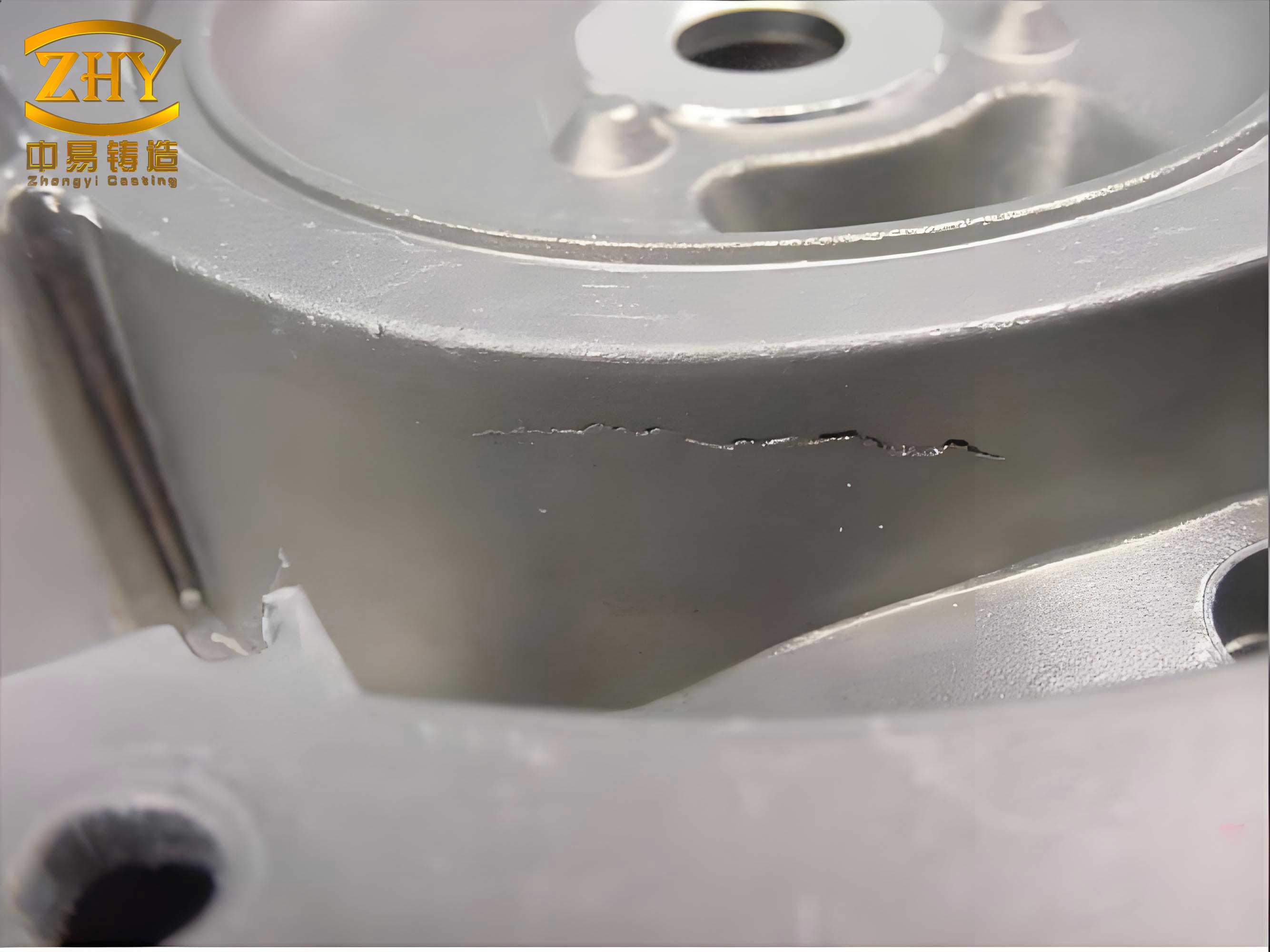
Shrinkage porosity is arguably the most critical defect in these load-bearing sockets. It manifests as irregular, coarse-walled cavities in the last-to-freeze regions, typically under the feeder (riser) or at thermal junctions like the cross-rib sections. This defect severely reduces the effective load-bearing cross-section. The primary driver is inadequate liquid metal feeding during the solidification sequence. The volume deficit caused by liquid shrinkage and solidification shrinkage must be compensated by feeder heads. The total shrinkage volume \( V_{shrink} \) can be estimated as:
$$ V_{shrink} = V_{casting} \times (\beta_{liquid} + \beta_{solidification}) $$
where \( V_{casting} \) is the volume of the casting, \( \beta_{liquid} \) is the liquid contraction coefficient (typically ~1.5% for steel), and \( \beta_{solidification} \) is the solidification shrinkage coefficient (approximately 3-4% for carbon steels). If the feeder system cannot supply this volume, shrinkage voids form. The key factors leading to this include:
- Obstructed Feeding Channels: The design of the socket often features intersecting ribs that create isolated hot spots. If the solidifying skin progresses in a way that cuts off liquid metal paths from the feeder to these hot spots, micro-shrinkage or macro-shrinkage occurs.
- Inadequate Feeder Design: An undersized or insufficient number of feeders fails to create the necessary thermal gradient for directional solidification toward the feeder. The feeder’s modulus \( M_{feeder} \) must be greater than the modulus of the casting section it is intended to feed \( M_{casting} \). The modulus is the volume-to-surface-area ratio \( M = V/A_s \). A common rule is \( M_{feeder} > 1.2 \times M_{casting} \).
- Excessive Pouring Temperature: While necessary for fluidity, an overly high superheat increases the total heat content, enlarges the mushy zone, and amplifies the shrinkage volume, making feeding more challenging. It also promotes gas dissolution.
- Poor Feeder Efficiency: If the feeder solidifies before the casting, “reverse feeding” occurs. The thermal efficiency of a feeder is enhanced by using insulating or exothermic sleeves, which maintain a liquid reservoir for longer.
The following table summarizes the causes and related parameters for shrinkage defects:
| Root Cause | Governing Principle/Parameter | Effect on Defect Formation |
|---|---|---|
| Poor Feeding Path Design | Thermal Gradient (G) & Solidification Rate (R) | Low G/R ratio promotes pasty solidification, isolating liquid pools. |
| Inadequate Feeder Size | Feeder Modulus \( M_f = V_f / A_{sf} \) | If \( M_f < 1.2 M_c \), feeder solidifies prematurely. |
| High Pouring Temperature (Tpour) | Total Superheat ΔT = Tpour – Tliquidus | Increases shrinkage volume \( \Delta V \propto \Delta T \), expands mushy zone. |
| Low Feeder Efficiency | Feeder Yield \( Y = V_{feed metal} / V_{feeder} \) | Conventional feeders have low Y (<14%). Insulating/exothermic feeders can double Y. |
Gas porosity is another pervasive category of casting defects, presenting as smooth-walled, often spherical cavities within the casting wall or near the surface. These can be classified broadly into precipitation porosity and entrainment porosity. The former results from gases like hydrogen and nitrogen precipitating from the molten steel upon cooling, as their solubility decreases drastically. Sievert’s law describes the solubility of diatomic gases in molten metals:
$$ S = k \sqrt{P_{gas}} $$
where \( S \) is the solubility (cm3/100g metal), \( k \) is the equilibrium constant (temperature-dependent), and \( P_{gas} \) is the partial pressure of the gas. During cooling and solidification, the solubility in the solid \( S_s \) is much lower than in the liquid \( S_l \). The rejected gas forms bubbles. If the solidification front velocity is high, these bubbles are trapped, creating numerous small, dispersed pores. The hydrogen content is particularly critical, as even a few ppm can cause significant porosity. The second type, entrainment porosity, arises from gas invasion from the mold. As the metal fills the mold, the intense heat causes moisture evaporation, binder breakdown, and combustion of additives, generating substantial gas pressure \( P_{moldgas} \). If the mold gas pressure exceeds the metallostatic pressure \( P_{metal} = \rho g h \) at the metal-mold interface, gas can be forced into the solidifying metal. Additionally, turbulent filling can entrap air from the gating system or mold cavity. This often manifests as larger, subsurface blowholes, especially in poorly vented pockets like the socket’s lug sections.
A summary of gas porosity mechanisms is presented below:
| Type of Gas Porosity | Source of Gas | Formation Mechanism | Key Influencing Factors |
|---|---|---|---|
| Precipitation (Microporosity) | Dissolved H2, N2 in melt | Decreasing solubility during cooling \( \frac{dS}{dT} > 0 \). | Melt cleanliness, humidity of charge, deoxidation practice, cooling rate. |
| Entrainment/Invasion (Macroporosity) | Mold atmosphere, binder decomposition | \( P_{moldgas} > P_{metal} + \sigma / r \) (capillary pressure). | Sand permeability, moisture/content, venting, pouring speed, mold coating. |
| Reaction Porosity | CO from C-O reaction in melt/mold | C (metal) + O (metal/mold) → CO (gas). | High carbon equivalent, oxidizing conditions, poor deoxidation. |
Metal penetration, or burn-on, is a surface casting defect where a tenacious layer of fused sand and metal adheres to the casting. It occurs when molten metal or metal oxides penetrate into the interstices between sand grains. The penetration depth \( \delta \) can be modeled by considering the metal as a fluid infiltrating a porous medium, approximated by Darcy’s law and capillary pressure:
$$ \delta \approx \sqrt{\frac{2 \gamma_{lv} \cos \theta \cdot t}{\mu \cdot f(\phi)}} $$
where \( \gamma_{lv} \) is the liquid-vapor surface tension, \( \theta \) is the contact angle, \( t \) is the contact time, \( \mu \) is the metal viscosity, and \( f(\phi) \) is a function of sand porosity and permeability. High metal temperature, low sand density (high porosity), and low refractoriness of the sand mixture promote this defect. It leads to poor surface finish, difficult cleaning, and potential stress raisers if not completely removed.
The prevention of these casting defects requires a systematic approach targeting each stage of the process: pattern and mold design, metallurgy, molding, and pouring. For shrinkage porosity, the cornerstone is achieving sound directional solidification. This is accomplished through strategic use of chills to increase the local cooling rate and designing efficient feeding systems. Computer simulation (Solidification Modeling) is now indispensable for optimizing feeder placement and size, predicting hot spots, and visualizing temperature gradients. The use of advanced feeder technologies—insulating sleeves, exothermic toppings, and atmospheric pressure feeders—dramatically improves feeding yield. The pouring practice must adhere to the “high-temperature melting, low-temperature pouring” principle. A lower superheat reduces the total shrinkage and narrows the mushy zone. Furthermore, “feeder topping” is crucial: as the metal rises to the feeder neck, the pouring rate is slowed, and hot metal is poured directly into the feeder, which is then covered with exothermic compound or charcoal to delay its solidification. Manual prodding of the feeder liquid breaks the initial skin, enhancing atmospheric pressure feeding.
To combat gas-related casting defects, a multi-front strategy is essential. In melting, all charge materials and tools must be dry and preheated. Effective deoxidation is non-negotiable. For steel, final deoxidation with aluminum is standard, as it forms Al2O3 inclusions which also act as nucleation sites for gas bubbles, facilitating their removal. The amount of aluminum required can be estimated based on the oxygen potential. After tapping, a sufficient holding (stilling) time in the ladle allows bubbles to float out. In mold design, an open, pressurization-balanced gating system ensures non-turbulent filling. Adequate venting is critical; vents and permeability in core prints must be designed to allow gas escape. The sand mixture must be controlled: using high-purity silica sand with low clay content, minimizing water glass addition (optimally below 8%), and ensuring proper mulling and compaction to achieve uniform, high permeability while maintaining adequate strength. The permeability number \( P \) is a key metric, given by:
$$ P = \frac{V \cdot H}{A \cdot t \cdot p} \times \text{constant} $$
where \( V \) is the volume of air passing through a sand specimen of height \( H \) and area \( A \) in time \( t \) under pressure \( p \). Higher \( P \) reduces back pressure but must be balanced against strength requirements. Applying refractory mold coatings (zircon-based) creates a barrier between the metal and sand, significantly reducing gas generation and metal penetration.
Preventing metal penetration focuses on creating a dense, refractory mold surface. This involves using sands with higher refractoriness (e.g., chromite or zircon sand for critical sections), achieving high and uniform mold hardness through proper ramming or shooting, and applying those effective mold washes. Lowering the pouring temperature within the fluidity limit reduces the thermal load and metal fluidity, thereby decreasing penetration tendency. The sand grain size distribution is also vital; a well-graded sand packs more densely, reducing pore size. The AFS Grain Fineness Number (AFS GFN) should be selected appropriately—too fine a sand may reduce permeability, while too coarse may increase penetration.
The following table consolidates the primary preventive and corrective measures for the key casting defects discussed:
| Target Defect | Process Stage | Preventive Action | Technical Rationale / Formula |
|---|---|---|---|
| Shrinkage Porosity | Design/Simulation | Use CAD/CAE to optimize feeder size & placement. Apply chills. | Ensure \( M_f > 1.2 M_c \), maximize temperature gradient G. |
| Molding | Use insulating/exothermic feeder sleeves. | Increase feeder yield \( Y \), delay \( t_{solidification, feeder} \). | |
| Melting/Pouring | Control superheat ΔT. Practice feeder topping & prodding. | Minimize \( V_{shrink} \). Maintain liquid feed path \( t_{path} > t_{casting solid} \). | |
| Alloy | Ensure proper composition (C, Cr) to control freezing range. | Narrow freezing range promotes planar solidification, easier feeding. | |
| Gas Porosity | Melting | Dry charge, preheated tools. Full deoxidation (Al addition). Ladle holding. | Minimize initial gas content \( [H]_0 \). Promote bubble nucleation & flotation. |
| Mold Design | Design open, turbulent-free gating. Adequate vents & permeability. | Ensure \( P_{metal} > P_{moldgas} \) throughout filling. Provide escape paths. | |
| Sand Preparation | Control water glass < 8%, use low-clay sand, optimal compaction. | Reduce gas generation per unit volume \( Q_{gas} \). Maintain permeability \( P \). | |
| Process Control | Apply mold coatings. Control sand moisture and binder content. | Create barrier, reduce interfacial gas generation rate \( \dot{Q}_{interface} \). | |
| Metal Penetration (Burn-on) | Sand Selection | Use high-refractoriness sands (e.g., Zircon) for facing. | Increase fusion point \( T_{fusion, sand} > T_{metal} \). |
| Molding | Achieve high, uniform mold hardness. Apply refractory coatings. | Reduce sand porosity \( \phi \) and average pore radius \( r_{pore} \). | |
| Pouring | Optimize pouring temperature to minimum for complete filling. | Reduce metal fluidity \( 1/\mu \) and contact time \( t \), per penetration equation. |
In conclusion, the battle against casting defects in water glass sand casting for critical components is a multifaceted engineering endeavor. It transcends traditional rule-of-thumb practices, demanding a scientific understanding of the underlying physical and chemical phenomena—fluid dynamics, heat transfer, solidification kinetics, and gas-metal interactions. The industry’s shift towards digitalization, with computer-aided engineering (CAE) for solidification and stress simulation, and the adoption of advanced molding materials and feeder technologies, has transformed the landscape. These tools allow for predictive analysis and optimization before metal is ever poured, significantly reducing the trial-and-error approach. Furthermore, stringent process control protocols, from raw material inspection to final pouring parameters, are vital. By integrating these modern techniques with fundamental metallurgical and foundry principles, we can systematically suppress the formation of shrinkage porosity, gas porosity, and metal penetration. This holistic approach not only enhances the internal soundness and surface quality of hydraulic support sockets but also elevates the overall reliability and safety of the mining equipment they constitute. The continuous pursuit of perfection in controlling these casting defects is, therefore, a cornerstone of quality assurance in heavy equipment manufacturing, ensuring that these critical components perform reliably under the extreme conditions of underground mining.