
In the realm of metal casting, ductile iron stands out as a high-strength ferrous material achieved through spheroidization and inoculation treatments that transform graphite morphology into spherical shapes. This transformation significantly enhances mechanical properties, particularly plasticity and toughness, rendering its performance close to that of steel. Consequently, ductile iron is extensively employed for parts subjected to complex stresses and demanding requirements for strength, toughness, and wear resistance. However, the inherent characteristic of ductile iron—exhibiting substantial expansion before contraction and significant eutectic expansion during solidification—poses a persistent challenge: the propensity for shrinkage defects such as shrinkage porosity and cavities in sand casting processes. This issue, often termed as shrinkage in casting, is exacerbated in components like housings or shells with irregular geometries, where non-destructive testing methods like ultrasonic inspection are less effective. Defects frequently emerge only after machining or during pressure testing in assembly, leading to increased production costs, quality claims, and delivery penalties, thereby tarnishing brand reputation. This article delves into a detailed investigation aimed at resolving shrinkage in casting in a specific ductile iron housing, presenting a first-person account of the analytical and corrective journey.
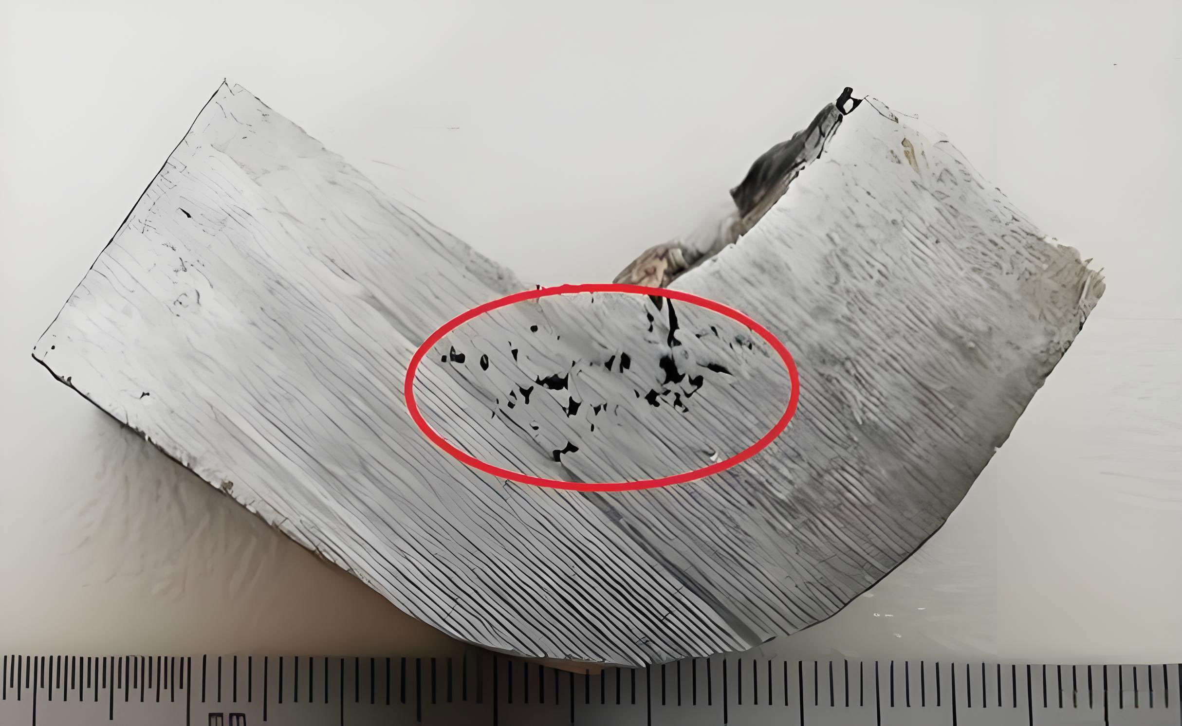
The housing casting under study, with a rough weight of 32 kg per piece and material grade QT500-7, was produced using green sand HWS high-pressure molding, KL61 exothermic risers, electric furnace melting, and wire-feeding spheroidization treatment. The initial process involved four castings per mold with a total pouring weight of 175 kg, and a pouring temperature range of 1360–1380°C. Despite these standardized parameters, the occurrence of shrinkage in casting defects was alarmingly high during trial and small-batch production phases, affecting over 30% of parts. Defects manifested as top shrinkage cavities, shrinkage porosity in plunger holes, and leakage in high-pressure oil passages after machining and assembly pressure tests.
To systematically address this shrinkage in casting issue, a multi-faceted approach was adopted, combining empirical observations with computational simulations. MAGMA software was utilized to simulate solidification and predict shrinkage tendencies. The simulation revealed critical risk zones, such as the top section and mid-walls where high-pressure oil channels are machined, indicating localized hot spots that solidified last, thereby increasing susceptibility to shrinkage in casting. The analysis pinpointed several root causes: suboptimal carbon equivalent (CE) limiting graphitization expansion, excessive pouring temperature aggravating liquid contraction, inadequate riser design failing to provide sufficient feeding, and unresolved thermal concentrations in the casting geometry.
The primary factors contributing to shrinkage in casting in this case are summarized in the table below, which contrasts initial conditions with optimized targets:
| Factor | Initial Condition | Optimized Target | Impact on Shrinkage in Casting |
|---|---|---|---|
| Carbon Equivalent (CE) | ~4.5% | 4.55–4.65% | Low CE reduces graphitization expansion, hindering self-feeding and increasing shrinkage in casting risk. |
| Pouring Temperature | 1360–1380°C | 1340–1350°C | High temperature increases liquid contraction, while too low may cause poor spheroidization; balanced temperature minimizes shrinkage in casting. |
| Riser Thermal Modulus | 1.6 cm (KL61 riser) | 1.9 cm (KL86 riser) | Insufficient modulus limits feeding capacity, leading to top shrinkage cavities, a direct form of shrinkage in casting. |
| Local Hot Spots | Present in side walls | Eliminated via conformal chills | Hot spots delay solidification, creating porosity; chills accelerate cooling to prevent shrinkage in casting. |
| Top Machining Allowance | Standard | Increased by 2 mm | Enhances material for riser feeding, reducing surface shrinkage and shrinkage in casting defects. |
Carbon equivalent plays a pivotal role in controlling shrinkage in casting. For ductile iron, CE is calculated as:
$$ CE = \%C + \frac{1}{3}(\%Si + \%P) $$
where C, Si, and P represent the weight percentages of carbon, silicon, and phosphorus, respectively. A higher CE, particularly near the eutectic point (around 4.6–4.7% for ductile iron), promotes graphite precipitation during solidification, generating expansion that counteracts liquid and solidification shrinkage. This self-feeding effect is crucial to mitigate shrinkage in casting. The initial low CE of approximately 4.5% was inadequate, so adjustments were made to raise the base iron carbon content to 3.80–3.85% and post-inoculation CE to 4.55–4.65%. This enhancement leverages the graphitization potential to combat shrinkage in casting.
Pouring temperature is another critical variable influencing shrinkage in casting. While higher temperatures improve fluidity and riser feeding, they also increase the liquid contraction volume, as described by the linear shrinkage coefficient. The total volumetric shrinkage during cooling can be approximated by:
$$ V_{shrinkage} = V_0 \cdot \alpha \cdot \Delta T $$
where \( V_0 \) is the initial volume, \( \alpha \) is the volumetric thermal contraction coefficient (typically around \( 1 \times 10^{-4} \, \text{K}^{-1} \) for iron alloys), and \( \Delta T \) is the temperature drop. Reducing the pouring temperature from 1360–1380°C to 1340–1350°C decreases \( \Delta T \), thereby lowering \( V_{shrinkage} \) and the severity of shrinkage in casting. However, care was taken to maintain sufficient superheat to avoid spheroidization degradation, ensuring a balance to prevent shrinkage in casting without compromising metallurgical quality.
Riser design is essential for compensating shrinkage in casting. The thermal modulus \( M \), defined as the volume-to-surface area ratio, determines riser efficiency:
$$ M = \frac{V}{A} $$
where \( V \) is volume and \( A \) is surface area. A higher modulus indicates slower cooling and better feeding. Initially, KL61 risers with \( M = 1.6 \, \text{cm} \) proved insufficient, as evidenced by top shrinkage cavities. Upgrading to KL86 risers with \( M = 1.9 \, \text{cm} \) enhanced feeding capacity. Additionally, the top machining allowance was increased by 2 mm to provide extra material for riser action, further reducing shrinkage in casting risks. The relationship between riser modulus and feeding demand can be expressed as:
$$ M_{riser} \geq k \cdot M_{casting} $$
where \( k \) is a safety factor (often 1.2 for ductile iron), and \( M_{casting} \) is the modulus of the hot spot. For the housing, simulations indicated hot spot moduli up to 1.5 cm, necessitating risers with \( M \geq 1.8 \, \text{cm} \), justifying the KL86 selection to address shrinkage in casting.
Localized hot spots are prime initiators of shrinkage in casting. In this housing, MAGMA simulations identified a thermal concentration in the side wall, corresponding to the high-pressure oil passage area. To eliminate this, conformal chills were developed. Chills work by extracting heat rapidly, modifying the solidification sequence to prevent isolated liquid pools. The heat extraction rate can be modeled using Fourier’s law:
$$ q = -k \cdot \frac{dT}{dx} $$
where \( q \) is heat flux, \( k \) is thermal conductivity, and \( \frac{dT}{dx} \) is the temperature gradient. By placing chills with high thermal conductivity (e.g., steel) against the mold wall, the gradient increases, accelerating cooling in the hot spot zone. This intervention effectively redistributed solidification fronts, reducing the time during which shrinkage in casting could form. The chills were coated and dried to prevent adhesion and gas defects, ensuring robustness in production.
The implementation of these measures—CE adjustment, temperature control, riser optimization, and chill application—was validated through small-batch trials. Results showed a complete elimination of visible shrinkage defects and no leakage during subsequent machining and pressure testing. To quantify the improvements, the table below compares key metrics before and after optimization:
| Metric | Before Optimization | After Optimization | Improvement |
|---|---|---|---|
| Shrinkage Defect Rate | >30% | 0% (in trials) | 100% reduction in shrinkage in casting |
| Carbon Equivalent | ~4.5% | 4.60% (average) | Enhanced graphitization expansion |
| Pouring Temperature | 1370°C (avg) | 1345°C (avg) | Reduced liquid contraction |
| Riser Modulus | 1.6 cm | 1.9 cm | Better feeding capacity |
| Hot Spot Severity | High (simulation) | Eliminated (chills) | Prevented localized shrinkage in casting |
| Production Yield | Low due to rework | High, stable for mass production | Cost savings and quality assurance |
Furthermore, the interplay between process parameters and shrinkage in casting can be analyzed using empirical models. For instance, the tendency for shrinkage porosity \( P \) in ductile iron may be correlated with factors like CE, pouring temperature \( T_p \), and modulus difference \( \Delta M \) between riser and casting:
$$ P = \beta_0 + \beta_1 \cdot (CE_{opt} – CE) + \beta_2 \cdot (T_p – T_{opt}) + \beta_3 \cdot \Delta M + \epsilon $$
where \( \beta_i \) are coefficients, \( CE_{opt} \) and \( T_{opt} \) are optimal values, and \( \epsilon \) is error. In this case, aligning parameters toward optima minimized \( P \), effectively controlling shrinkage in casting. The success underscores that a holistic approach, rather than isolated tweaks, is vital to mitigate shrinkage in casting.
In conclusion, addressing shrinkage in casting in ductile iron components requires a deep understanding of material behavior and process dynamics. Key lessons include: maintaining carbon equivalent near the eutectic point to harness graphitization expansion; optimizing pouring temperature to balance fluidity and contraction; designing risers with adequate thermal modulus for effective feeding; and employing chills to eliminate thermal concentrations. Each measure contributes to reducing the risk of shrinkage in casting, as demonstrated in this housing case. Future work could explore advanced simulation techniques or real-time monitoring to further refine these strategies. Ultimately, proactive management of these factors enables reliable production of high-integrity castings, minimizing defects like shrinkage in casting and enhancing overall manufacturing efficiency.
The journey from defect analysis to solution highlights the importance of iterative testing and simulation. For instance, additional formulas can describe solidification kinetics relevant to shrinkage in casting. The solidification time \( t_s \) for a section can be estimated using Chvorinov’s rule:
$$ t_s = B \cdot \left( \frac{V}{A} \right)^2 = B \cdot M^2 $$
where \( B \) is a mold constant. By increasing \( M \) via risers or reducing \( B \) via chills, \( t_s \) is modulated to ensure directional solidification toward feeders, thereby preventing shrinkage in casting. Moreover, the volume of shrinkage compensation required \( V_{comp} \) can be derived from the alloy’s shrinkage characteristic:
$$ V_{comp} = f_s \cdot V_{casting} \cdot \varepsilon $$
where \( f_s \) is the solidification shrinkage fraction (about 4–6% for ductile iron), and \( \varepsilon \) is a safety factor. This guides riser sizing to address shrinkage in casting. Through such engineering principles, the battle against shrinkage in casting is won, paving the way for quality-driven casting practices.