
In my extensive experience with investment casting, I have consistently encountered shrinkage porosity as a pervasive and challenging defect that compromises the integrity of precision components. This defect, characterized by dispersed micro-porosity within the casting’s thick sections, axis areas, and near gates, often remains hidden until machining or testing, leading to significant scrap rates and quality concerns. The fundamental cause, as I have observed, is the inability to provide adequate liquid metal feeding to localized hot spots during solidification. Through years of practice and analysis, I have identified that effective solutions revolve around ensuring sufficient feed metal volume, establishing and maintaining open feeding channels, and optimizing the thermal environment. This article delves into the root causes of shrinkage in investment casting and presents systematic solutions, incorporating empirical data, theoretical models, and practical tables to guide foundry engineers. Investment casting, with its unique advantages for complex geometries, demands meticulous attention to these factors to achieve sound, defect-free castings.
The investment casting process, renowned for its ability to produce intricate, near-net-shape parts with excellent surface finish, involves creating a ceramic shell around a wax pattern. After dewaxing and firing, molten metal is poured into the preheated shell. However, the very nature of this process—using hot molds and often complex part designs—creates inherent challenges for directional solidification and feeding. My work has shown that shrinkage porosity arises primarily when the volume contraction of the solidifying metal is not compensated by incoming liquid from the feeding system. This can be quantified by considering the solidification shrinkage rate, typically 3-6% for steels and other alloys used in investment casting. The required feed metal volume \( V_f \) can be expressed as:
$$ V_f = \varepsilon \cdot V_c $$
where \( \varepsilon \) is the volumetric shrinkage coefficient and \( V_c \) is the volume of the casting section that solidifies last. If the feeding system cannot deliver \( V_f \), porosity forms. Furthermore, the thermal gradient \( \nabla T \) is critical; a steep gradient promotes directional solidification toward the feeder, while a flat gradient leads to isolated hot spots and shrinkage. The thermal gradient can be influenced by shell properties, casting geometry, and cooling conditions.
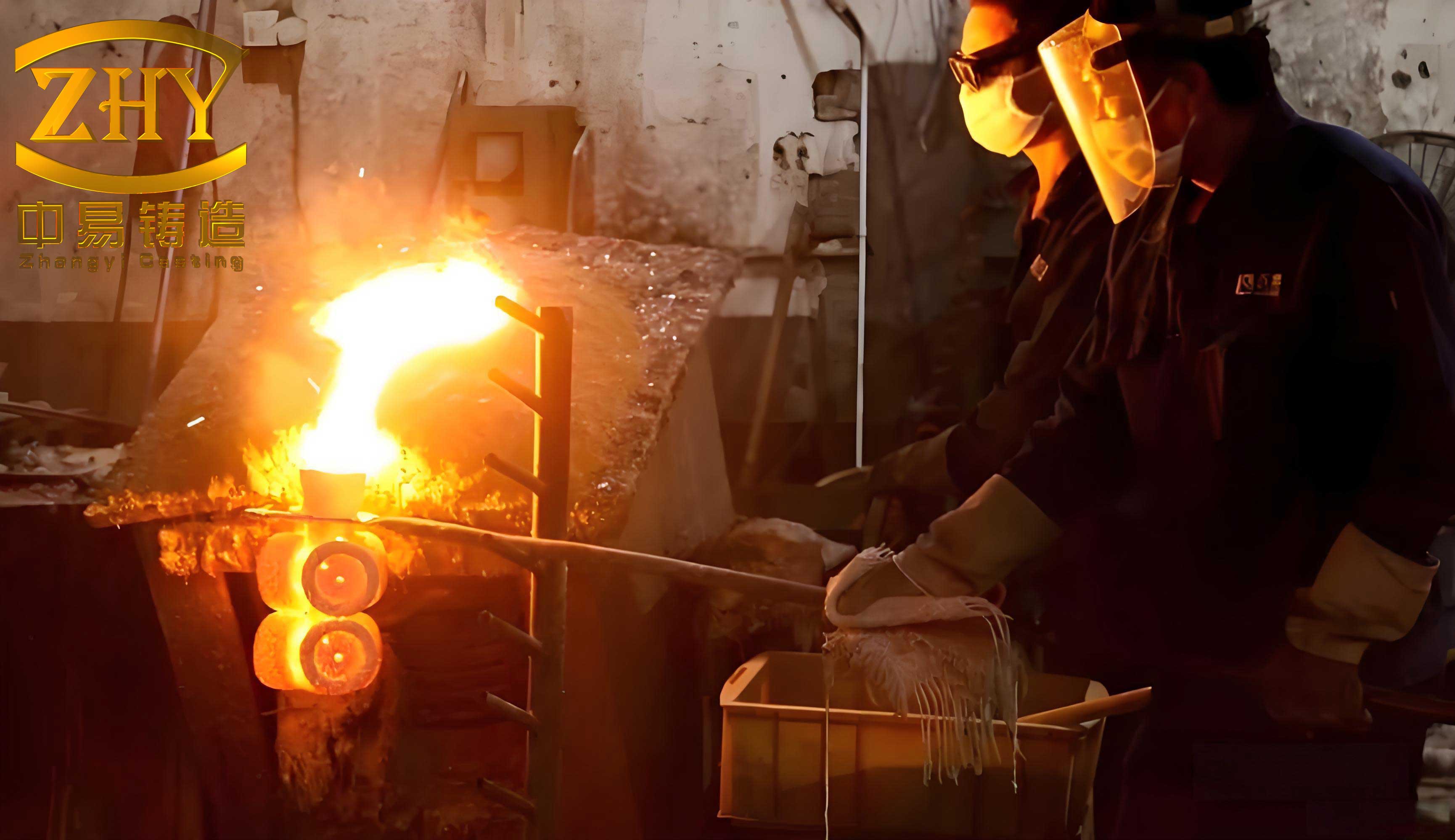
One of the most common issues I’ve diagnosed in investment casting operations is insufficient metallostatic head pressure. When the pouring cup is not filled completely, the effective pressure head \( h \) for feeding is reduced, diminishing the driving force for liquid metal to flow into shrinking regions. The feeding pressure \( P_f \) is given by:
$$ P_f = \rho g h $$
where \( \rho \) is the molten metal density and \( g \) is acceleration due to gravity. If \( P_f \) falls below the threshold needed to overcome the resistance in the feeding channels (especially in thin sections or long paths), shrinkage occurs. For instance, in a series of valve body castings, I found that simply ensuring the pouring cup was overfilled by 20% increased the yield of sound castings by 15%. This highlights the importance of rigorous pour control in investment casting. To generalize, I recommend maintaining a minimum head height \( h_{min} \) calculated based on the casting’s longest feeding distance \( L_f \) and the alloy’s fluidity. A practical rule I use is:
$$ h_{min} = k \cdot L_f $$
where \( k \) is an empirical factor ranging from 0.5 to 2.0, depending on alloy and shell temperature.
Castings with problematic geometries are a frequent source of shrinkage in investment casting. Features like isolated heavy sections, abrupt changes in wall thickness, and internal recesses create “thermal hotspots” that solidify last and are difficult to feed. From my projects, I recall a flange component where a recessed groove acted as a thermal barrier, blocking the feeding path from the main feeder. By redesigning the part to eliminate the groove (adding machining stock), the feeding channel was opened, and shrinkage was eliminated. This aligns with the principle of maintaining a progressive solidification front. The modulus \( M \), defined as the volume-to-surface area ratio \( \frac{V}{A} \), is a useful tool for predicting hot spots. Areas with higher modulus solidify slower. In investment casting, we aim to design feeders with a modulus greater than that of the casting hot spot, typically by a factor of 1.1 to 1.2. The solidification time \( t_s \) can be estimated using Chvorinov’s rule:
$$ t_s = C \left( \frac{V}{A} \right)^2 = C M^2 $$
where \( C \) is a constant dependent on mold material and metal properties. By calculating moduli for different sections, we can identify potential shrinkage zones and design adequate feeders. The following table summarizes common geometric issues and redesign strategies in investment casting:
| Geometric Feature | Shrinkage Risk | Redesign Solution | Modification Principle |
|---|---|---|---|
| Isolated thick flange | High – creates isolated hot spot | Add a feeding riser or increase connecting wall thickness | Increase feeder modulus \( M_f > M_c \) |
| Deep, narrow pocket | High – acts as thermal barrier | Fill pocket with ceramic core or modify to open shape | Reduce local modulus, improve heat extraction |
| Thin wall between thick sections | Medium – freezes early, blocking feed | Increase thin wall thickness or use chilling | Balance solidification rates, maintain feed path |
| Internal web or rib | Medium – creates junction hot spot | Add fillets or reduce rib thickness | Reduce junction modulus, promote directional solidification |
The ceramic shell itself can be a significant contributor to shrinkage defects in investment casting. A shell with poor permeability traps gases and inhibits heat transfer, slowing solidification and exacerbating shrinkage. In one case, a part with long, slender internal channels consistently showed porosity. The issue was that the shell-building process completely plugged these channels with stucco, creating massive internal hot spots. The solution was to redesign the gating to treat the channel as solid and place feeders accordingly. The permeability \( K \) of a shell is a function of pore structure and can be approximated for laminar flow as:
$$ K = \frac{\phi d^2}{180 (1 – \phi)^2} $$
where \( \phi \) is porosity and \( d \) is mean particle diameter. Low \( K \) values lead to back pressure and reduced feeding efficiency. I advocate for using coarser stucco in primary layers for heavy sections and adding permeability enhancers like graphite fibers to the slurry. Another shell-related issue is localized thickening in tight crevices, which increases the thermal mass and creates hot spots. For such investment casting components, pre-cooling the shell in specific areas by water spraying before pouring can dramatically improve the thermal gradient.
Incorrect gating and riser design is a pervasive error I’ve rectified in many investment casting shops. An improperly placed ingate can itself become a hot spot, causing shrinkage at its root. For example, a thick casting initially gated at its edge exhibited severe shrinkage at the gate junction. By relocating the ingate to a central position and incorporating a choke, we achieved better thermal balance. The gating design must ensure that the feeder remains liquid longest. The feeding range \( R \) of a riser in investment casting is limited by the length over which adequate pressure can be maintained, often described by:
$$ R = \sqrt{\frac{2 P_f}{\rho g \alpha}} $$
where \( \alpha \) is a resistance factor for the mushy zone. Exceeding this range leads to shrinkage. Furthermore, the shape of the ingate matters. A wedge-shaped ingate on a thin flange solidified too quickly, failing to feed. Changing it to a rectangular section with greater cross-sectional area sustained feeding longer. The following formula helps determine the minimum ingate cross-section \( A_g \) to prevent premature freezing:
$$ A_g = \frac{V_f}{v t_f} $$
where \( v \) is the flow velocity and \( t_f \) is the local solidification time of the ingate. Using simulation software, I now routinely optimize feeder dimensions and placement to ensure \( A_g \) is sufficient and the thermal center is properly controlled.
Inadequate cooling conditions are a subtle but critical factor in investment casting shrinkage. The investment shell is typically preheated to high temperatures (often above 900°C for steel) to prevent thermal shock, but this also slows overall cooling, allowing hot spots to persist. I have seen castings that developed porosity simply because clusters of shells were placed too close together after pouring, creating an oven-like effect. Strategic cooling is essential. Techniques I employ include: placing castings on cooling racks for air circulation, burying shells in dry sand to promote uniform cooling, or even directed water quenching of specific heavy sections. The heat transfer from the casting can be modeled using the Fourier equation. The rate of heat extraction \( Q \) is proportional to the temperature difference and the effective heat transfer coefficient \( h_{eff} \):
$$ Q = h_{eff} A (T_c – T_\infty) $$
where \( T_c \) is casting temperature and \( T_\infty \) is ambient temperature. By increasing \( h_{eff} \) through forced air or localized chilling, we can steepen the thermal gradient. In one project for a large pump housing, applying copper chills to thick flanges reduced the local solidification time by 30% and eliminated subsurface shrinkage. The table below contrasts common cooling methods in investment casting and their impact on shrinkage risk:
| Cooling Method | Application | Effect on Heat Transfer Coefficient \( h_{eff} \)** | Impact on Shrinkage |
|---|---|---|---|
| Still air cooling (standard) | General practice | Low (5-25 W/m²K) | High risk for heavy sections |
| Forced air cooling | Targeted on hot spots | Moderate (25-100 W/m²K) | Reduces risk significantly |
| Dry sand embedding | Entire shell after pour | Low to Moderate (10-30 W/m²K) | Promotes uniformity, reduces cracking but may increase risk if too insulating |
| Water spray/quench | Localized heavy sections pre/post-pour | High (500-10,000 W/m²K) | Dramatically reduces risk, but can cause stress |
| Metallic chills (copper/iron) | Embedded in shell at hot spots | Very High (1000-20000 W/m²K) | Most effective for eliminating isolated hot spots |
Blocked feeding channels are perhaps the most straightforward yet overlooked cause of shrinkage in investment casting. A feeding channel that freezes before the section it is supposed to feed is useless. This often happens when a thin section (like a web) connects a feeder to a hot spot; the thin section solidifies first, isolating the hot spot. In a valve cover casting, shrinkage occurred at two flanges because the connecting channel was too long and restrictive. The solution involved both insulating the feeder to keep it liquid longer and chilling the lower flange to create a temperature gradient that drew feed metal toward the upper flange. The concept of “feeding path efficiency” \( \eta_f \) can be defined as the ratio of the time the path remains open to the solidification time of the hot spot:
$$ \eta_f = \frac{t_{path}}{t_{hotspot}} $$
We aim for \( \eta_f > 1 \). This can be achieved by increasing the modulus of the feeding path or by using exothermic or insulating toppings on feeders. Another effective technique I use is adding “feed aids” or washable cores that create temporary channels which are removed post-casting. These are especially useful in complex investment casting geometries where natural feeding paths are tortuous.
Beyond these primary causes, the alloy composition and melt quality play a role in shrinkage susceptibility in investment casting. Some alloys have a wider freezing range, which promotes a mushy zone that is difficult to feed. For such alloys, even with good gating, shrinkage may occur interdendritically. The well-known Niyama criterion, often used in simulation, helps predict shrinkage porosity based on local thermal conditions:
$$ G / \sqrt{\dot{T}} $$
where \( G \) is the temperature gradient and \( \dot{T} \) is the cooling rate at the solidus front. Values below a critical threshold indicate a high risk of microporosity. In investment casting, we can influence this by controlling shell preheat temperature and pouring temperature. A lower pour temperature can reduce total heat content and shrink the mushy zone, but must be balanced against fluidity requirements. My practice is to use “high temperature melting, low temperature pouring” for heavy-section investment castings to minimize shrinkage.
To synthesize the solutions, a holistic approach is required for successful investment casting. The process begins with part design review, using modulus calculations and solidification simulation to identify risks. Then, the gating system is designed to provide adequate feed metal volume and pressure. The shell-making process must ensure sufficient permeability, especially in critical areas. Finally, controlled cooling strategies are implemented to establish favorable thermal gradients. The integration of these steps can be summarized by a master equation for shrinkage avoidance, which combines key parameters:
$$ S_{index} = \frac{\varepsilon V_c}{A_g v t_f} \cdot \frac{1}{K} \cdot \frac{T_{shell}}{h_{eff}} $$
where a lower \( S_{index} \) indicates a lower risk of shrinkage. By systematically minimizing each term—through design, process control, and cooling—we can drive this index down. Investment casting, with its versatility, demands such a disciplined methodology to consistently produce high-integrity castings.
In conclusion, my journey in tackling shrinkage porosity in investment casting has taught me that there is no single magic bullet. It is a multifaceted problem requiring a deep understanding of heat transfer, fluid flow, and material science. The key lies in ensuring that every thermal hotspot receives adequate liquid metal feed until it solidifies. This is achieved by a combination of intelligent part design, robust gating and risering, optimized shell properties, and active thermal management. Investment casting will continue to evolve, and with advanced tools like real-time thermal monitoring and AI-driven simulation, our ability to predict and prevent shrinkage will only improve. However, the fundamental principles outlined here—focusing on feeding pressure, channel openness, and heat extraction—remain the cornerstone of quality in the investment casting industry. By sharing these insights, I hope to contribute to the collective knowledge that pushes the boundaries of what is possible in precision metal casting.