
The production of high-integrity, complex-shaped aluminum castings for critical applications, such as housings in Gas Insulated Switchgear (GIS), presents significant manufacturing challenges. Low-pressure die casting (LPDC) is often the preferred method for these shell castings due to its superior filling control and mechanical properties compared to gravity casting. However, the inherent complexity of such shell castings, characterized by varying wall thicknesses and intricate geometries, frequently leads to solidification defects like shrinkage porosity and hot tears. Traditionally, process optimization relied heavily on costly and time-consuming trial-and-error methods. The integration of computational solidification simulation into the foundry workflow has revolutionized this approach, enabling the virtual prediction of defects and the systematic refinement of gating and cooling systems before any metal is poured. This article details a comprehensive study where simulation-driven analysis was employed to diagnose and eliminate shrinkage defects in a critical GIS aluminum shell casting.
The subject component was a ZL101A-T6 aluminum alloy GIS housing. Its key features included a cylindrical body with two integral flanges. Ensuring pressure tightness and a good internal surface finish for the machined bore were paramount quality requirements. The initial low-pressure casting process utilized a sand mold with three ingates: one located at the smaller flange and two at the larger flange. To promote directional solidification, chills were employed. The specific configuration of these chills, particularly around the large flange, was initially identified as the root cause of the defects. The table below summarizes the primary characteristics of the casting and the initial process layout.
| Feature | Description |
|---|---|
| Material | ZL101A-T6 Aluminum Alloy |
| Casting Mass | 40 kg |
| Nominal Wall Thickness | 12 mm |
| Casting Method | Sand Mold Low-Pressure Casting |
| Number of Ingates | 3 (1 at small flange, 2 at large flange) |
| Initial Chill Design (Large Flange) | 25mm thick conformal chill ring |
| Observed Defect Post-Machining | Shrinkage porosity/cavities on the cylindrical wall near the large flange. |
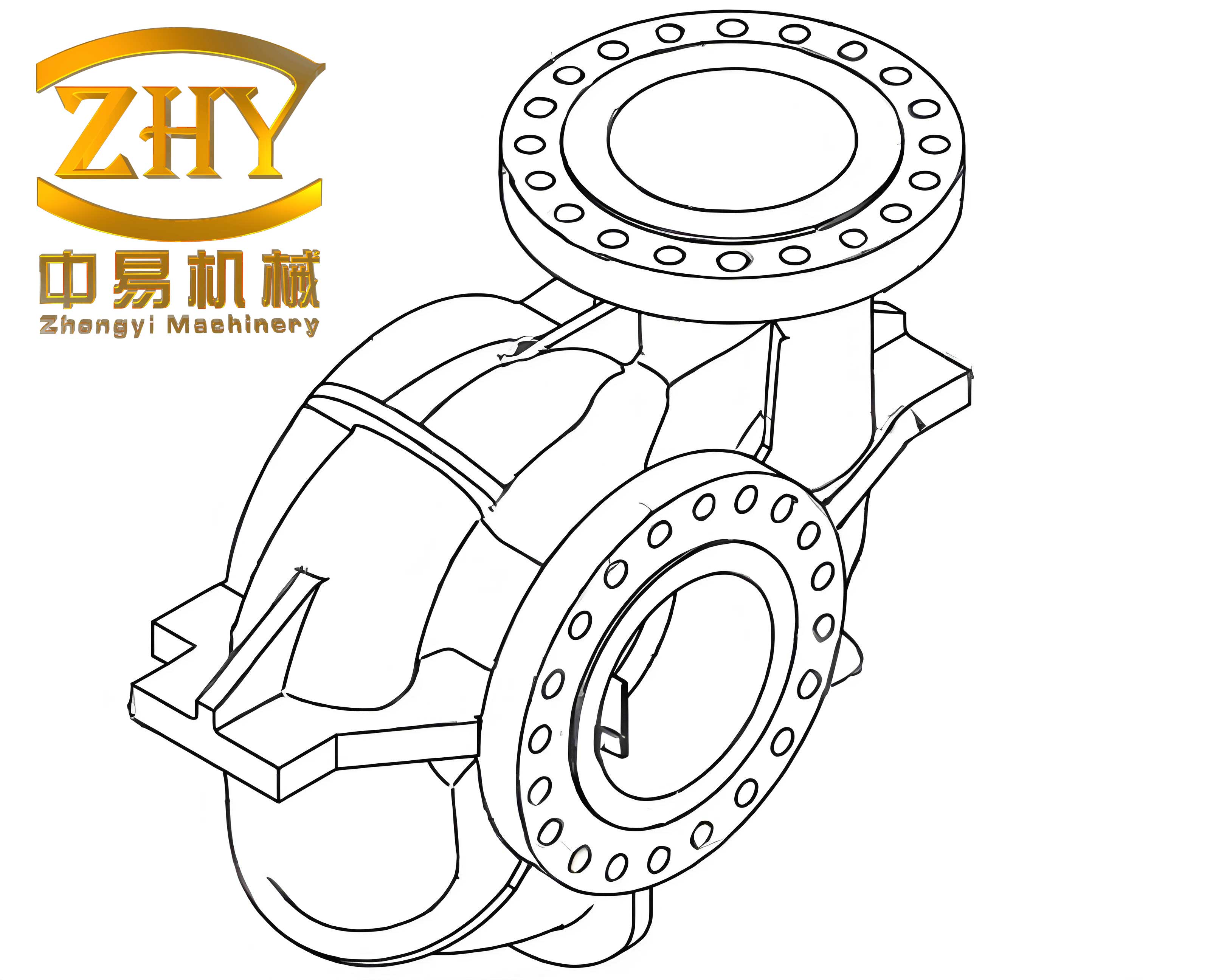
Despite strict adherence to the established process protocol, a persistent defect was observed after machining. The machined internal surface of the cylindrical section, particularly in the region adjacent to the large flange, exhibited scattered shrinkage porosity. This defect was unacceptable for the functional requirements of the GIS shell castings. To understand the root cause, a full solidification simulation of the initial process was conducted using commercial casting simulation software (ProCAST). The simulation parameters were set to accurately model the thermal behavior of the system, as detailed in the following table.
| Simulation Parameter | Value / Setting |
|---|---|
| Casting Material | ZL101A |
| Pour Temperature | 700 °C |
| Mold Material | Silica Sand |
| Initial Mold Temperature | 50 °C |
| Heat Transfer Coefficient (Casting-Sand) | 500 W/(m²·K) |
| Heat Transfer Coefficient (Casting-Chill) | 1000 W/(m²·K) |
| Heat Transfer Coefficient (Chill-Mold) | 500 W/(m²·K) |
The simulation of the filling stage showed a smooth, progressive fill from the bottom upwards, with no evident turbulent entrapment of air or oxides. This ruled out gas-related defects as the primary cause, focusing the investigation squarely on the solidification dynamics. The analysis of the solidification sequence and the prediction of shrinkage using the Niyama criterion were revealing. The Niyama criterion ($Ny$) is a widely used function of local thermal parameters to predict shrinkage porosity. It is expressed as:
$$Ny = \frac{G}{\sqrt{\dot{T}}}$$
where $G$ is the temperature gradient (°C/m) and $\dot{T}$ is the cooling rate (°C/s). Regions with a Niyama value below a critical threshold are prone to shrinkage porosity. The simulation results for the initial process clearly indicated a high-risk band of shrinkage around the cylindrical wall, aligning perfectly with the defect locations found in the physical shell castings.
The critical insight came from analyzing the solidification time contours. The simulation revealed that the thick (25mm) conformal chill on the large flange face acted as an extremely effective heat sink. This caused the metal in the ingate regions and their immediate vicinity to solidify prematurely, much earlier than the main cylindrical wall section. The thermal analysis demonstrated the formation of an isolated liquid pocket. Once the ingates and the adjacent channels froze, the remaining liquid in the central portion of the cylinder wall was completely cut off from the feeding source (the riser or pressurized liquid in the biscuit). As this isolated volume solidified and underwent natural volumetric shrinkage, there was no liquid metal available to compensate, inevitably leading to the formation of a shrinkage cavity. The fundamental heat extraction issue can be described by Fourier’s law of heat conduction. The heat flux ($q$) from the casting into the chill is given by:
$$q = -k \cdot A \cdot \frac{dT}{dx}$$
where $k$ is the thermal conductivity of the chill, $A$ is the contact area, and $\frac{dT}{dx}$ is the temperature gradient. The initial chill’s large thickness and full conformal contact resulted in a very high effective $kA$ product, extracting heat too rapidly from specific locations and disrupting the desired thermal gradient. The shrinkage volume ($V_{shrinkage}$) in such an isolated region can be conceptually related to the volumetric shrinkage of the alloy ($\beta$) and the isolated liquid volume ($V_{liquid}$):
$$V_{shrinkage} \approx \beta \cdot V_{liquid}$$
This diagnostic analysis pinpointed the problem: the original chill design was too aggressive, preventing the establishment of a progressive, directional solidification pattern from the extremities of the shell castings back towards the ingates and ultimately to the feeder.
Based on this understanding, the process was optimized virtually. The goal was to moderate the cooling rate near the large flange to prevent premature sealing of the feeding paths while still ensuring adequate cooling to achieve soundness. The optimized design involved two key changes to the large flange chill:
- Reduce the chill thickness from 25mm to 15mm.
- Reconfigure the chill ring to be non-conformal: it was pulled back to create a 10mm gap from the cylindrical wall and was also notched or “set back” to avoid direct contact with the locations of the two ingates.
This redesign significantly altered the thermal dynamics. The reduced thickness lowered the chilling power (reducing the $kA$ product in the simplified model). The 10mm gap introduced an additional thermal resistance (an air/sand layer) between the chill and the critical cylindrical wall, further dampening the initial intense cooling on that area. By keeping the chill away from the ingates, the local solidification time at these critical feeding points was extended. The table below contrasts the key parameters of the initial and optimized chill designs for the large flange area.
| Parameter | Initial Process | Optimized Process |
|---|---|---|
| Chill Thickness | 25 mm | 15 mm |
| Geometry | Full Conformal Ring | Set-Back Ring with Gap |
| Distance from Cylinder Wall | 0 mm (in contact) | 10 mm gap |
| Relationship to Ingates | Directly covers ingate locations | Cleared from ingate locations |
| Primary Thermal Effect | Very high, localized extraction | Moderate, more distributed extraction |
A new simulation was run with the optimized geometry. The results were markedly different. The solidification time plot now showed a continuous, progressive gradient. The cylindrical wall and the ingate regions remained thermally connected for a much longer duration. Solidification proceeded sequentially from the isolated ends of the shell castings towards the ingates, ensuring a continuous liquid feed path to compensate for shrinkage throughout the entire process. The Niyama criterion prediction showed a complete elimination of the high-risk shrinkage band in the cylindrical wall. The thermal gradient $G$ was now maintained favorably along the feeding direction, keeping the $Ny$ value above the critical threshold in all areas of the casting.
To validate the simulation findings, the optimized process was implemented in actual production. Multiple shell castings (over ten pieces) were produced using the new chill design with a 15mm thickness, a 10mm setback from the wall, and clearance for the ingates. After undergoing the standard production sequence—casting, cleaning, heat treatment (T6), and finally, machining—the components were inspected. The result was a significant quality improvement. The internal machined surfaces of the cylindrical walls were sound and free from the shrinkage porosity that had plagued the initial batches. The yield rate for acceptable castings rose to over 95%, confirming that the simulation accurately predicted the real-world behavior and that the optimization was effective.
The successful resolution of this issue underscores several key principles in the manufacturing of complex shell castings:
- The Power of Simulation: Numerical simulation moved the problem-solving phase from the foundry floor to the computer, saving substantial time, material, and cost associated with physical trials.
- Thermal Management is Critical: The function of chills is not merely to cool but to strategically shape the solidification front. Over-chilling can be as detrimental as under-chilling, as it can create isolated liquid zones.
- Feeding Path Integrity: Maintaining an open liquid metal feed path to compensate for volumetric shrinkage until the final moment of solidification is paramount. Any premature freezing in the feeding network will lead to defects.
- Directional Solidification Control: The ultimate goal for sound shell castings is to establish a controlled, directional solidification pattern that ensures liquid feed is always available from a designed source.
In conclusion, this case study demonstrates a robust methodology for tackling solidification defects in critical low-pressure die cast aluminum shell castings. By employing computational solidification simulation to diagnose the formation of an isolated liquid pocket caused by an overly aggressive chill, a targeted optimization was developed. The solution involved reducing chill thickness and strategically repositioning it to moderate local cooling rates. This adjustment successfully transformed the solidification pattern from one prone to shrinkage defects to one characterized by sequential solidification, thereby eliminating the porosity. The physical production results validated the simulation predictions, highlighting the essential role of virtual engineering in modern, efficient, and high-quality casting production for demanding applications like GIS components.