
In the demanding field of oil and gas engineering, the reliability of critical components is non-negotiable. Among these, large gear housings serve as foundational structures, housing intricate gear trains that transmit substantial power. The casting of such components presents significant challenges, with slag inclusion standing out as a particularly persistent and costly defect. This article details a first-hand engineering journey to diagnose and eliminate pervasive slag inclusion defects in an HT200 gray iron gear housing. The casting, with dimensions of 2322 mm × 1595 mm × 762 mm and a weight of 2350 kg, suffered from an unacceptably high scrap rate primarily due to inclusions found on critical machined surfaces. Through systematic process analysis, targeted modifications, and rigorous validation, we achieved a dramatic reduction in scrap, transforming the production viability of this essential component.
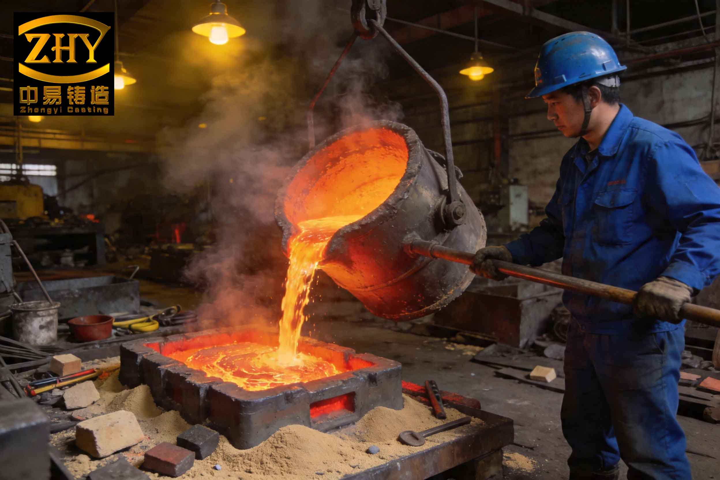
The initial production process employed a horizontally-poured, bottom-gated system within a large flask (3000 mm x 3000 mm). The molds were created using hand-made furan resin sand cores. Despite this conventional approach, the post-casting machining operations revealed severe slag inclusion defects, concentrating on two main areas: the upper plane of the housing and, more critically, the internal end faces of the low-, medium-, and especially the high-speed shaft bores. These are all functional machined surfaces where any inclusion is grounds for rejection. The financial impact was substantial, with external scrap rates initially observed at levels that threatened the project’s economic feasibility.
Root Cause Analysis: A Multifaceted Problem
A thorough investigation pinpointed several convergent factors contributing to the slag inclusion problem. It is crucial to understand that slag inclusion defects originate from the entrapment of non-metallic particles—such as slag, dross, sand, or refractory fragments—within the casting matrix. The driving forces are often a combination of turbulence, insufficient slag trapping, and unfavorable geometry.
The primary reasons identified were:
- Inadequate Slag Management at Source: Incomplete cleaning of the ladle and pouring basin allowed exogenous particles to be introduced into the metal stream at the very beginning of the pour.
- Ineffective Filtration: The ceramic foam filters used in the original gating system were not providing the necessary level of filtration fineness or thermal shock resistance, allowing fine slag particles to pass through or fragments of the filter itself to break off.
- Poor Slag Flotation and Trapping within the Mold: The design of the gating system and the mold cavity itself did not facilitate the effective separation and capture of slag. The locations of the defects were telling:
- Upper Plane Defects: Indicated that slag, having a lower density than molten iron, floated to the highest point but was not efficiently diverted into a safe overflow or riser.
- Shaft End Face Defects: These regions, particularly the high-speed shaft end, often represent “dead zones” or low-flow areas in the cavity. Slag particles transported by the metal flow can settle in these calm areas as the velocity drops. The original small overflow pieces attached to the core were insufficient in volume and strategic placement to act as effective slag traps for these zones.
The fluid dynamics can be partially described by Stokes’ law, governing the rise velocity of a spherical particle in a liquid, which is critical for understanding slag flotation:
$$
v_t = \frac{2}{9} \frac{(\rho_f – \rho_p) g r^2}{\eta}
$$
Where \( v_t \) is the terminal velocity (m/s), \( \rho_f \) is the fluid (iron) density, \( \rho_p \) is the particle (slag) density, \( g \) is gravity, \( r \) is the particle radius, and \( \eta \) is the dynamic viscosity of iron. A smaller particle radius \( r \) drastically reduces the rise velocity \( v_t \), meaning fine slag particles may not have enough time to float out of the metal before solidification if the geometry and thermal conditions are not favorable.
A Systematic Portfolio of Corrective Actions
The solution required a multi-pronged attack, addressing each root cause from metal entry to final solidification.
1. Enhanced In-Mold Slag Collection: Strategic Overflow Design
The first line of defense within the mold itself was reinforced. The main sand core (1# core) was modified to incorporate significantly larger and more numerous overflow pieces. These are essentially blind cavities or extensions connected to areas prone to slag inclusion. Their purpose is to provide a low-resistance path for the contaminant-laden first metal to flow into, where it solidifies harmlessly and is later removed.
| Feature | Original Process | Improved Process | Function |
|---|---|---|---|
| Quantity | Limited, insufficient coverage | 12 strategically placed pieces | Increase probability of capturing slag from multiple flow paths. |
| Location | Generic placement | Specifically positioned near high-risk zones like shaft end faces and upper sections | Intercept slag before it settles in critical areas. |
| Volume | Small | Substantial (e.g., 13mm x 70mm x 80mm) | Provide sufficient capacity to hold contaminated metal without backing up into the casting. |
This modification ensured that the initial, oxide-rich metal front and entrained slag were proactively diverted away from the casting body, fundamentally reducing the source of slag inclusion inside the cavity.
2. Redundancy via Strategic Machining Allowance
Recognizing that perfect filtration and flotation is an ideal, a pragmatic mechanical redundancy was introduced. On the internal end faces of the high-speed shaft—the most problematic location—the machining allowance was strategically increased. A raised pad, 15 mm in height and 30 mm in width, was added to the casting design in these specific areas.
The principle is straightforward: any residual slag inclusion that manages to settle in this “sacrificial” zone is guaranteed to be removed during the normal machining operation that establishes the final face dimension and finish. This acts as a final, reliable safety net for quality. The depth of cut \( d_{cut} \) must satisfy:
$$
d_{cut} \geq h_{slag} + \Delta
$$
Where \( h_{slag} \) is the expected maximum depth of the slag inclusion defect zone, and \( \Delta \) is a safety margin. By designing \( h_{allowance} = 15mm \), we ensured \( d_{cut} > h_{slag} \) was always true under production variations.
3. Upgraded Filtration: From Ceramic to Advanced Foam
The gateway to the mold cavity—the filter—was critically evaluated. Ceramic filters, while common, can sometimes exhibit limitations in fine-particle retention or thermal stability. We upgraded to a high-grade rigid foam filter with superior characteristics:
- Higher Filtration Fineness: Smaller pore size for capturing finer slag particles.
- Improved Thermal Shock Resistance: Reduced risk of filter fracture and the introduction of ceramic fragments as a new source of slag inclusion.
- Better Flow Characteristics: A more controlled, less turbulent transition from the gating system to the mold cavity.
The effectiveness of a filter can be related to its pore size distribution and the contaminant particle size. The filtration efficiency \( \eta_f \) for particles of diameter \( d_p \) can be conceptually modeled (simplified) as increasing sharply when \( d_p \) approaches the filter’s mean pore diameter \( d_{pore} \):
$$
\eta_f \propto 1 – \exp\left(-k \left(\frac{d_p}{d_{pore}}\right)^m\right)
$$
Where \( k \) and \( m \) are constants dependent on filter morphology. Upgrading to a filter with a smaller \( d_{pore} \) shifts this curve, capturing a greater fraction of smaller particles that would otherwise cause slag inclusion.
4. Thermal Management for Slag Flotation: Premium Riser Upgrade
To tackle the slag inclusion on the upper surfaces, the thermal and feeding dynamics were modified. Two high-efficiency insulating risers were added on the long-axis external faces of the housing. These risers served a dual purpose:
- Prolonged Liquid Life: The insulating sleeve significantly reduces heat loss, keeping the metal in the riser liquid for a much longer time than a conventional sand-backed riser. This extended time, governed by the solidification time \( t \) via Chvorinov’s Rule, is critical:
$$
t = B \left( \frac{V}{A} \right)^n
$$
Where \( V \) is volume, \( A \) is surface area, \( n \) is a constant (~2), and \( B \) is the mold constant. An insulating riser increases the effective \( B \) for the riser itself, making \( t_{riser} >> t_{casting} \). - Slag Migration Path: With the riser remaining molten longest, it creates a sustained thermal and physical “sink” for buoyant slag particles. The extended time allows even particles with a slow rise velocity \( v_t \) to travel the distance from the casting body into the riser, where they are safely concentrated and later removed.
| Action | Component | Mechanism | Targeted Defect Location |
|---|---|---|---|
| Add Strategic Overflows | 1# Sand Core | Diverts initial dirty metal flow into blind traps. | All internal cavity surfaces, especially dead zones. |
| Increase Machining Allowance | High-Speed Shaft End Face | Provides a sacrificial layer for mechanical removal of any residual inclusion. | Specific high-risk machined faces. |
| Upgrade Filter Medium | Gating System | Improves mechanical interception of fine slag particles at the mold entrance. | Entire casting (prevents entry). |
| Install Insulating Riser | Top of Casting / Long Faces | Extends liquid duration to promote buoyancy-driven slag flotation into a safe reservoir. | Upper planes and top sections of casting. |
Results and Quantitative Impact
The implementation of this combined strategy yielded transformative results. The modifications were validated over a sustained production run. The most critical metric—the scrap rate due to slag inclusion and related defects—plummeted from an initial, unsustainable level of approximately 33% down to a remarkable 4.3%. This represents a reduction in scrap by nearly 87%.
The financial implications are profound. For a high-value, material- and labor-intensive casting like this gear housing, salvaging 28-29 out of every 100 pieces previously scrapped directly translates to massive savings in material, energy, and machining costs. Furthermore, the consistency and reliability of the supply chain were restored, meeting the stringent demands of the oil and gas sector.
Conclusion and Foundry Philosophy
The successful resolution of the severe slag inclusion problem in this complex gear housing underscores a fundamental principle in foundry engineering: defect prevention is a holistic system challenge, not a single-step fix. The journey from a 33% to a 4.3% scrap rate was not achieved by one magical change but through a sequenced, scientifically-informed series of interventions:
- Prevent Entry: Upgrading the filter acts as the first barrier.
- Divert Contaminants: Strategic overflows inside the mold collect the initial contaminated metal.
- Promote Natural Separation: Insulating risers leverage the laws of physics (buoyancy and thermal gradients) to draw slag away from the casting.
- Build in Redundancy: Strategic increases in machining allowance provide a fail-safe mechanical removal for the most stubborn risk areas.
This case study exemplifies that combating slag inclusion requires a deep understanding of fluid flow, solidification dynamics, and practical foundry techniques. It demonstrates that by viewing the mold cavity, gating system, and thermal controls as an integrated system designed to manage impurities, even the most challenging casting quality problems can be systematically solved, yielding both exceptional quality and significant economic return.