
In my extensive experience with lost foam casting, I have consistently observed that slag inclusions represent a critical challenge that can compromise the integrity and quality of cast components. This advanced casting method, often hailed as a revolutionary technique in the metallurgical industry, involves the use of foam patterns that vaporize upon contact with molten metal. While it offers significant advantages in terms of design flexibility and reduced post-processing, the process is susceptible to various defects, with slag inclusions being particularly prevalent and detrimental. These defects manifest as non-metallic inclusions within the cast structure, often visible after machining as white or grayish spots, which can severely affect mechanical properties and surface finish. Through this article, I aim to delve deeply into the mechanisms behind slag inclusions, leveraging empirical data and theoretical models, and provide a detailed, actionable framework for mitigation. The discussion will incorporate quantitative analyses via formulas and tabulated summaries to enhance clarity and practical application.
The term “slag inclusions” in lost foam casting broadly encompasses both sand particles (often referred to as sand inclusions) and other non-metallic residues such as coating debris, foam pyrolysis products, and oxides. These contaminants are entrained during the pouring process, leading to localized stress concentrations and potential failure points. A visual representation of such defects can be seen below, illustrating typical manifestations in cast surfaces.
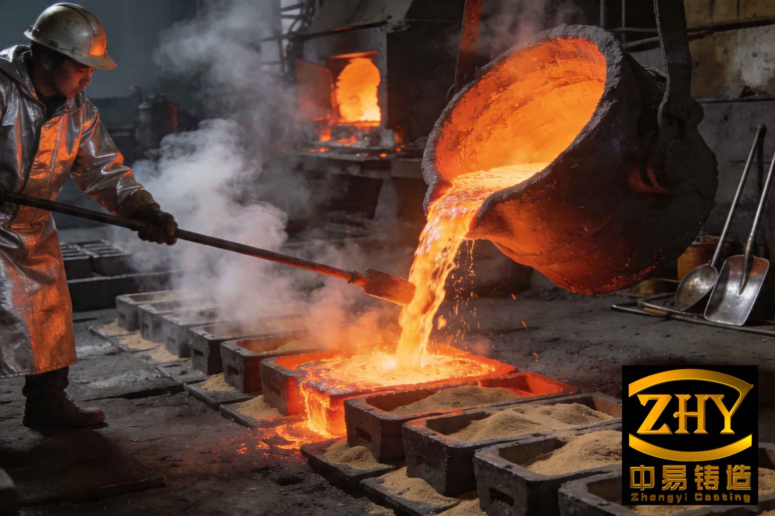
From a fundamental perspective, the formation of slag inclusions is intrinsically linked to the dynamic interaction between the molten metal, the foam pattern, the coating layer, and the unbonded sand mold. When the liquid metal fills the cavity, the polystyrene pattern undergoes thermal degradation, producing gaseous and liquid by-products. If the coating applied to the pattern lacks sufficient integrity, it can crack or spall, allowing sand grains or coating fragments to be washed into the metal stream. Additionally, improper sealing of the gating system or turbulent flow conditions can exacerbate the entrainment of impurities. In my observations, the prevalence of slag inclusions is often higher in flat or thin-walled castings, such as clutch plates or engine covers, where the flow dynamics are more prone to disturbance. To systematically address this, I will first analyze the root causes, then explore mitigation strategies in detail, emphasizing the repeated importance of controlling slag inclusions through every stage of the process.
Fundamental Mechanisms and Contributing Factors to Slag Inclusions
The genesis of slag inclusions can be traced to multiple interrelated factors. Primarily, the coating layer serves as the first line of defense; its failure directly introduces contaminants. The coating must exhibit high strength, refractoriness, and thermal shock resistance to withstand the thermal and mechanical stresses during pouring. Mathematical modeling of coating stress under thermal load can be expressed using the following formula for thermal stress (\(\sigma_t\)):
$$ \sigma_t = E \cdot \alpha \cdot \Delta T / (1 – \nu) $$
where \(E\) is the Young’s modulus of the coating, \(\alpha\) is the coefficient of thermal expansion, \(\Delta T\) is the temperature gradient, and \(\nu\) is Poisson’s ratio. If \(\sigma_t\) exceeds the tensile strength of the coating, cracking occurs, leading to potential slag inclusions. Moreover, the gating system design influences flow velocity and turbulence. The Reynolds number (\(Re\)) helps assess flow regime:
$$ Re = \frac{\rho v D}{\mu} $$
where \(\rho\) is fluid density, \(v\) is velocity, \(D\) is hydraulic diameter, and \(\mu\) is dynamic viscosity. High \(Re\) values indicate turbulent flow, which increases the erosive force on coatings and the likelihood of entraining slag inclusions. Other key factors include pouring parameters, sand properties, and operational practices, all of which I will quantify in subsequent sections.
| Cause Category | Specific Factors | Impact Level (High/Medium/Low) | Typical Manifestation |
|---|---|---|---|
| Coating Integrity | Cracking, spalling, low strength, poor adhesion | High | Direct entry of sand and coating debris |
| Gating System | Poor sealing, sharp bends, inadequate rigidity | High | Turbulence and leakage at junctions |
| Pouring Parameters | Excessive pouring height, incorrect temperature | Medium | Increased erosion and thermal shock |
| Sand Properties | Coarse grain size, high dust content | Medium | Penetration into metal stream |
| Pattern Handling | Rough transportation, improper compaction | Low | Localized coating damage |
In addition to these, the degradation of the foam pattern itself generates residues that can contribute to slag inclusions. The pyrolysis kinetics can be described by an Arrhenius-type equation:
$$ k = A e^{-E_a/(RT)} $$
where \(k\) is the rate constant, \(A\) is the pre-exponential factor, \(E_a\) is activation energy, \(R\) is the gas constant, and \(T\) is temperature. Faster decomposition at higher temperatures may overwhelm the coating’s permeability, leading to pressure buildup and coating fracture. Thus, optimizing the coating to manage gas evolution is crucial to prevent slag inclusions.
Strategic Mitigation of Slag Inclusions Through Coating Optimization
To combat slag inclusions, enhancing coating performance is paramount. In my practice, I have developed coatings with tailored compositions to achieve a balance between strength and permeability. The coating must resist mechanical abrasion during sand filling and thermal stress during metal pouring. A key metric is the coating’s hot strength, which can be evaluated using a modified Weibull distribution for failure probability:
$$ P_f = 1 – \exp\left[-\left(\frac{\sigma}{\sigma_0}\right)^m\right] $$
where \(P_f\) is the probability of failure, \(\sigma\) is applied stress, \(\sigma_0\) is characteristic strength, and \(m\) is the Weibull modulus. Higher \(m\) values indicate more consistent coating quality, reducing sporadic slag inclusions. Furthermore, coating thickness (\(t_c\)) plays a role; too thin a layer may lack durability, while too thick can impede gas escape. An optimal range can be derived from empirical data, often between 0.5 and 1.5 mm, depending on alloy type. The relationship between coating thickness and defect rate for slag inclusions often follows a U-shaped curve, as modeled below:
$$ \text{Defect Rate} = a t_c^2 + b t_c + c $$
where \(a\), \(b\), and \(c\) are constants determined experimentally. By adjusting coating composition—such as incorporating refractory fillers like zirconia or alumina—the refractoriness can be improved, directly lowering the incidence of slag inclusions. Additionally, binder systems (e.g., colloidal silica or polymer binders) must be selected to provide green and dry strength. I typically recommend a multi-layered coating approach: a primer layer for adhesion and a topcoat for high-temperature resistance, which has proven effective in minimizing slag inclusions in complex castings.
| Coating Component | Recommended Type | Function | Optimal Percentage | Impact on Slag Inclusions |
|---|---|---|---|---|
| Refractory Filler | Zircon flour, Fused silica | Provides high-temperature resistance | 60-70% by weight | High – reduces erosion |
| Binder | Colloidal silica, Latex | Enhances strength and adhesion | 20-30% | High – prevents spalling |
| Additives | Surfactants, Anti-foam agents | Improves rheology and application | 1-5% | Medium – ensures uniformity |
| Carrier | Water, Alcohol | Medium for slurry | Adjust for viscosity | Low – indirect effect |
Beyond composition, the application process is critical. Uniform dipping or spraying ensures consistent coverage, especially at junctions like sprue-runner connections, which are prone to slag inclusions. Curing and drying must be controlled to avoid cracks; I often use a stepwise drying schedule with temperatures below 50°C to prevent foam distortion. The coating’s permeability, essential for gas escape, can be quantified by Darcy’s law:
$$ Q = \frac{k A \Delta P}{\mu L} $$
where \(Q\) is gas flow rate, \(k\) is permeability, \(A\) is area, \(\Delta P\) is pressure difference, \(\mu\) is gas viscosity, and \(L\) is coating thickness. A balanced permeability (typically \(10^{-12}\) to \(10^{-10}\) m²) allows gases to exit without compromising structural integrity, thereby reducing the risk of slag inclusions from coating failure.
Operational and Process Controls to Minimize Slag Inclusions
Even with an optimal coating, careless handling during molding and pouring can introduce slag inclusions. In my workflow, I emphasize meticulous box filling and vibration compaction. The pattern assembly, including gating, must be rigidly constructed—often using reinforcement ribs or glue reinforcements—to prevent flexing that cracks coatings. During sand filling, gentle initial vibration with low amplitude (e.g., 0.5-1.0 mm) is advised to embed the pattern without stress, followed by higher amplitudes for densification. The vibration frequency (\(f\)) and time (\(t_v\)) influence sand compaction density (\(\rho_s\)), which affects mold support:
$$ \rho_s = \rho_0 + K \cdot f \cdot t_v $$
where \(\rho_0\) is initial density and \(K\) is a material constant. Inadequate compaction can lead to mold collapse, increasing slag inclusions, while over-vibration may damage coatings. Moreover, the gating system must be designed to minimize turbulence. I often use tapered sprues and foam filters to streamline flow. The Bernoulli equation helps in designing gating dimensions to control velocity:
$$ \frac{P}{\rho g} + \frac{v^2}{2g} + z = \text{constant} $$
where \(P\) is pressure, \(v\) is velocity, \(g\) is gravity, and \(z\) is elevation. By maintaining a controlled pouring height (typically 100-200 mm for iron castings), the metal velocity is kept low, reducing erosive forces that cause slag inclusions. Pouring temperature is another critical variable; for gray iron, I recommend 1380-1420°C, as higher temperatures increase fluidity but also thermal aggression against coatings. The relationship between pouring temperature (\(T_p\)) and defect density (\(D_d\)) for slag inclusions can be approximated linearly in a range:
$$ D_d = \beta_0 + \beta_1 T_p $$
where \(\beta_0\) and \(\beta_1\) are coefficients derived from regression analysis. In many trials, \(\beta_1\) is positive, indicating that excessive temperature elevates slag inclusions risk.
| Alloy Type | Pouring Temperature Range (°C) | Optimal Negative Pressure (MPa) | Pouring Time for 500 kg (s) | Sand Grain Size (AFS) |
|---|---|---|---|---|
| Gray Iron | 1380-1420 | 0.025-0.04 | 10-20 | 30/50 |
| Ductile Iron | 1420-1450 | 0.03-0.045 | 15-25 | 40/70 |
| Carbon Steel | 1480-1560 | 0.04-0.06 | 20-30 | 50/100 |
| Aluminum Alloys | 700-750 | 0.01-0.02 | 5-15 | 70/140 |
Vacuum or negative pressure is a hallmark of lost foam casting, aiding in mold rigidity and gas removal. However, excessive vacuum can draw sand particles into the metal through coating cracks. The optimal negative pressure (\(P_v\)) for iron castings is around 0.025-0.04 MPa, as per my experience. This can be modeled using a pressure balance equation:
$$ P_v = P_a – \frac{\rho_m g h}{2} $$
where \(P_a\) is atmospheric pressure, \(\rho_m\) is metal density, \(g\) is gravity, and \(h\) is metal head height. Maintaining \(P_v\) within this range stabilizes the mold without promoting slag inclusions. Additionally, the use of slag-trapping mechanisms in the gating system, such as whirl gates or filter inserts, can capture impurities before they enter the cavity. The efficiency of a filter (\(\eta_f\)) in removing slag inclusions can be expressed as:
$$ \eta_f = 1 – \frac{C_{\text{out}}}{C_{\text{in}}} $$
where \(C_{\text{in}}\) and \(C_{\text{out}}\) are inclusion concentrations before and after filtration. Ceramic foam filters with pore sizes of 10-20 ppi (pores per inch) have shown \(\eta_f\) values above 0.8 in my tests, significantly reducing slag inclusions.
Advanced Techniques for Slag Inclusion Prevention and Metal Purification
Beyond basic controls, advanced metallurgical practices are essential to mitigate slag inclusions. Metal treatment prior to pouring, including degassing and fluxing, reduces the inherent oxide content that contributes to slag inclusions. For iron alloys, inoculants and nodularizers can improve metal cleanliness. The kinetics of inclusion floatation can be described by Stokes’ law:
$$ v_s = \frac{2 g r^2 (\rho_m – \rho_i)}{9 \mu} $$
where \(v_s\) is settling velocity, \(r\) is inclusion radius, \(\rho_m\) and \(\rho_i\) are densities of metal and inclusion, and \(\mu\) is metal viscosity. Larger inclusions rise faster, so promoting agglomeration through fluxes enhances removal. In my foundry, I often employ ladle refining with argon purging to float out slag inclusions; this is particularly effective for steel castings. Furthermore, real-time monitoring of pouring parameters using sensors can dynamically adjust conditions. A predictive model for slag inclusions risk (\(R_{si}\)) based on multiple variables can be developed using a multivariate equation:
$$ R_{si} = \alpha_1 X_1 + \alpha_2 X_2 + \alpha_3 X_3 + \cdots + \alpha_n X_n $$
where \(X_i\) represent factors like coating thickness, pouring temperature, vacuum level, etc., and \(\alpha_i\) are weighting coefficients determined through machine learning algorithms on historical defect data. Implementing such models has allowed me to preemptively adjust processes, cutting slag inclusions rates by over 30% in production runs.
Another innovative approach is the use of reactive coatings that absorb or dissolve impurities. For instance, coatings containing calcium carbonate can react with oxides to form low-melting-point slags that are easily separated. The reaction stoichiometry can be represented as:
$$ \text{CaCO}_3 \rightarrow \text{CaO} + \text{CO}_2 $$
$$ \text{CaO} + \text{SiO}_2 \rightarrow \text{CaSiO}_3 $$
This in-situ slag formation captures free oxides, preventing them from becoming embedded as slag inclusions. Additionally, post-casting inspections using non-destructive testing (e.g., ultrasonic or X-ray) help identify subsurface slag inclusions, guiding process corrections. The defect detection probability (\(P_d\)) as a function of inclusion size (\(d\)) follows a sigmoidal curve:
$$ P_d = \frac{1}{1 + e^{-k(d – d_0)}} $$
where \(k\) and \(d_0\) are constants. By correlating detected slag inclusions with process logs, continuous improvement cycles are established.
| Strategy Category | Specific Actions | Expected Reduction in Slag Inclusions | Implementation Difficulty | Key Metrics for Monitoring |
|---|---|---|---|---|
| Coating Enhancement | Optimized composition, multi-layer application | 40-60% | Medium | Coating strength, permeability |
| Process Optimization | Controlled pouring height, temperature, vacuum | 30-50% | Low | Pouring rate, defect count |
| Gating Design | Use of filters, tapered sprues, slag traps | 20-40% | Medium | Flow velocity, inclusion capture rate |
| Metal Treatment | Ladle refining, flux addition, argon purging | 25-45% | High | Oxide content, cleanliness index |
| Quality Control | NDT inspection, data analytics, real-time sensors | 15-30% | High | Detection rate, process variability |
In conclusion, addressing slag inclusions in lost foam casting requires a holistic, systems-based approach. From my firsthand experience, no single solution is sufficient; rather, a combination of robust coating technology, precise process control, intelligent gating, and thorough metal purification must be synergistically applied. The recurrence of slag inclusions can be dramatically reduced by adhering to the principles outlined here, with continuous monitoring and adaptation. As the industry moves toward more demanding applications, mastering the mitigation of slag inclusions will remain a cornerstone of quality assurance in lost foam casting. I encourage practitioners to integrate these insights into their workflows, leveraging quantitative models and empirical data to drive improvement. Ultimately, the battle against slag inclusions is won through diligence, innovation, and a deep understanding of the underlying physics and chemistry.
To further elaborate, the economic impact of slag inclusions cannot be overstated. Rejections due to these defects lead to material waste, increased production costs, and delays. By implementing the strategies discussed, foundries can achieve higher yield and customer satisfaction. Future research directions may focus on nanotechnology-enhanced coatings or AI-driven process automation to further minimize slag inclusions. In all cases, the key is to maintain a proactive stance, anticipating potential sources of slag inclusions at every step—from pattern making to final shakeout. Through persistent effort and technical rigor, the challenges posed by slag inclusions can be effectively managed, unlocking the full potential of lost foam casting as a superior manufacturing method.