
As a casting engineer specializing in advanced foundry processes, I have extensively worked with lost foam casting (LFC) for steel production. This technique, which involves using expendable foam patterns to create complex metal parts, offers significant advantages such as reduced machining, high dimensional accuracy, and environmental benefits. However, the application of LFC to steel casting introduces unique challenges, primarily due to the high temperatures involved and the interaction between the molten metal and the foam pattern. In this article, I will delve into the common casting defects encountered in lost foam casting of steel, analyze their root causes, and explore the factors influencing their occurrence. My goal is to provide a detailed reference for practitioners aiming to minimize these defects and enhance process reliability. Throughout this discussion, the term ‘casting defects’ will be frequently emphasized, as understanding and mitigating these issues is crucial for successful implementation.
The lost foam process fundamentally relies on the vaporization of a foam pattern during metal pouring. For steel, which has pouring temperatures typically ranging from 1500°C to 1600°C, the pattern decomposes rapidly, generating gases and residues that can lead to various casting defects if not properly managed. The primary casting defects in steel LFC include carbon pickup defects, gas porosity defects, and mold collapse defects. Each of these defects stems from specific interactions between the process parameters and the material properties. Below, I will systematically break down each defect category, supported by tables and formulas to summarize key relationships.
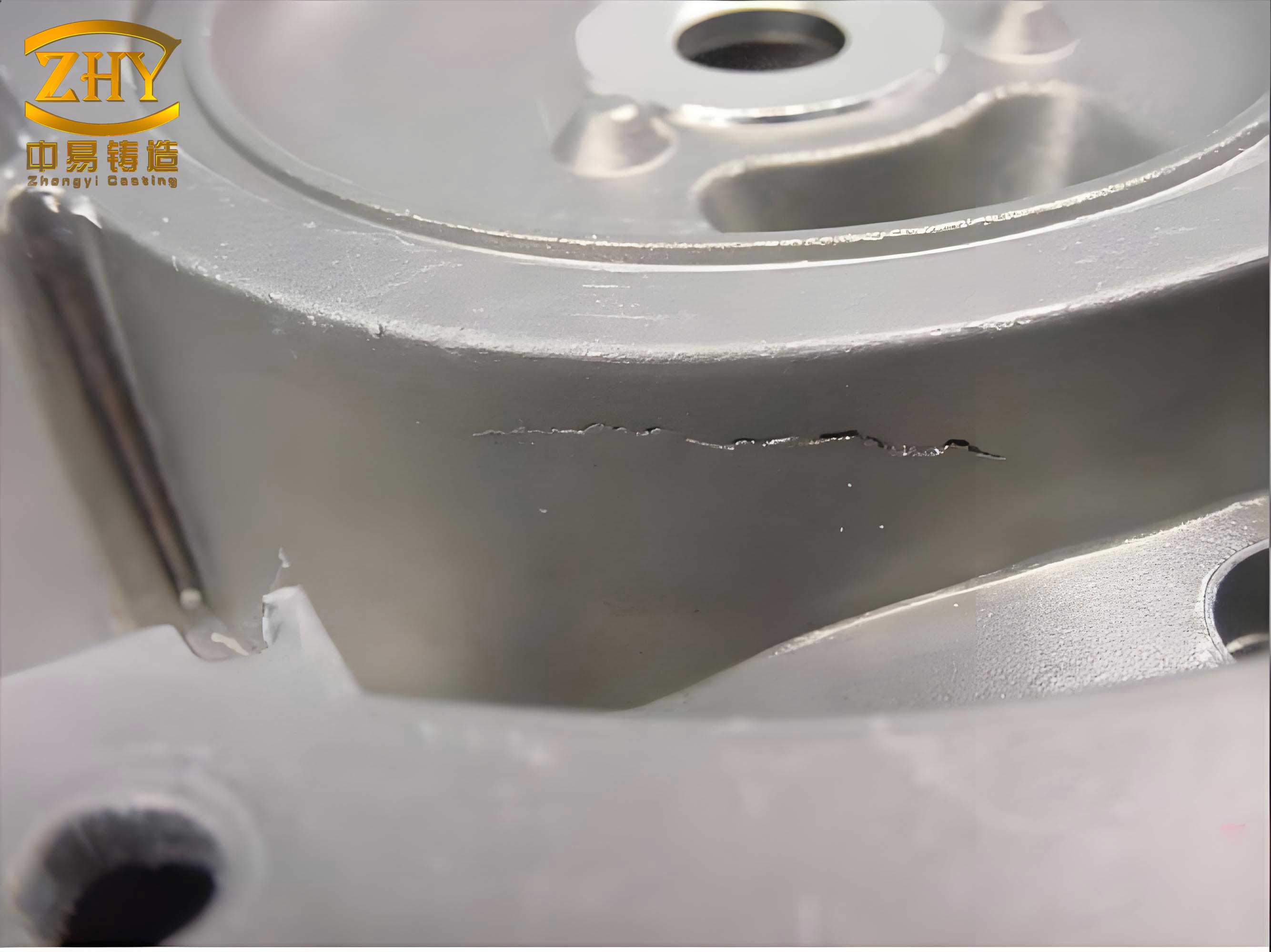
Carbon defects are among the most prevalent casting defects in steel lost foam casting. They manifest as an increase in carbon content on the surface or subsurface of the cast steel component, which can adversely affect mechanical properties, machinability, and weldability. The mechanism involves the decomposition of the foam pattern, which is typically made of hydrocarbons like expanded polystyrene (EPS), releasing carbon-rich gases, liquids, and solids that interact with the molten steel. The carbon diffusion into the steel surface is driven by concentration gradients and high temperatures. A simplified model for carbon diffusion can be expressed using Fick’s first law: $$ J = -D \frac{\partial C}{\partial x} $$ where \( J \) is the carbon flux (kg/m²·s), \( D \) is the diffusion coefficient of carbon in steel (m²/s), and \( \frac{\partial C}{\partial x} \) is the carbon concentration gradient (kg/m³·m). The negative sign indicates diffusion from high to low concentration. In practice, the carbon pickup \( \Delta C \) can be approximated by: $$ \Delta C = k \cdot t^{1/2} \cdot (C_p – C_s) $$ where \( k \) is a rate constant dependent on process conditions, \( t \) is the interaction time, \( C_p \) is the carbon potential from the pattern decomposition, and \( C_s \) is the initial carbon content in the steel. This relationship highlights that casting defects like carbon pickup are influenced by multiple factors, which I will detail later.
To illustrate the impact of pattern material on carbon defects, consider the following table based on experimental data. Different foam materials have varying carbon contents and decomposition behaviors, leading to distinct levels of casting defects.
| Pattern Material | Chemical Composition | Density (g/cm³) | Maximum Carbon Pickup (%) | Depth of Carbon Layer (mm) |
|---|---|---|---|---|
| Expanded Polystyrene (EPS) | (C₈H₈)ₙ, ~92% C | 0.02-0.03 | 0.31 | 0.70 |
| EPS-PMMA Copolymer (3:7 ratio) | Mixed polymer | 0.02-0.025 | 0.21 | 0.45 |
| Polymethyl Methacrylate (PMMA) | (C₅H₈O₂)ₙ, ~60% C | 0.02-0.03 | 0.14 | 0.37 |
| Low-Density EPS Variant | Modified EPS | 0.015-0.02 | 0.10 | 0.30 |
This table shows that PMMA, with lower carbon content, results in reduced carbon defects compared to EPS. Thus, selecting appropriate pattern materials is a critical step in mitigating these casting defects. Additionally, the initial steel composition plays a key role. Low-carbon steels (e.g., below 0.2% C) are more susceptible to carbon pickup due to steeper concentration gradients. For instance, a steel with 0.1% C may experience a carbon increase of 0.3% on the surface, while a steel with 0.45% C may show negligible pickup. This can be modeled by modifying the diffusion equation to account for the concentration difference: $$ \frac{\partial C}{\partial t} = D \frac{\partial^2 C}{\partial x^2} + S(x,t) $$ where \( S(x,t) \) represents a source term from pattern decomposition, which is higher for EPS than PMMA.
Gas porosity defects are another common category of casting defects in lost foam steel casting. These defects appear as voids or bubbles within the cast structure, often caused by trapped gases from the foam decomposition or air entrainment during pouring. The foam pattern, when heated, undergoes thermal degradation, producing volatile gases. The gas generation rate \( G \) can be estimated as a function of temperature \( T \): $$ G(T) = A \cdot e^{-E_a/(RT)} $$ where \( A \) is a pre-exponential factor, \( E_a \) is the activation energy for decomposition, \( R \) is the gas constant, and \( T \) is the absolute temperature. For EPS, gas generation increases exponentially with temperature, reaching up to 700 cm³/g at 1200°C. If these gases cannot escape quickly through the coating and sand mold, they may become entrapped in the solidifying metal, leading to porosity. The pressure buildup \( P \) in the mold cavity can be described by: $$ P = \frac{nRT}{V} $$ where \( n \) is the number of moles of gas, \( V \) is the cavity volume, and \( T \) is the temperature. Excessive pressure can contribute to both gas porosity and mold collapse defects.
The following table summarizes key factors influencing gas porosity defects, along with recommended controls to minimize these casting defects.
| Factor | Effect on Gas Porosity | Optimal Range for Steel Casting | Mitigation Strategy |
|---|---|---|---|
| Pattern Density | Higher density increases gas generation | 0.015-0.025 g/cm³ | Use low-density foam patterns |
| Coating Permeability | Low permeability traps gases | High permeability coatings | Adjust coating thickness (0.5-1.5 mm) |
| Pouring Temperature | Higher temperature accelerates gas generation | 1550-1600°C for typical steels | Optimize temperature to balance fluidity and gas evolution |
| Vacuum Pressure | Insufficient vacuum reduces gas extraction | 0.04-0.06 MPa negative pressure | Maintain consistent vacuum during pouring |
| Gating System Design | Poor design causes turbulent flow and gas entrapment | Bottom gating with tapered runners | Simulate flow to minimize turbulence |
Collapse defects, also known as mold wall collapse or buckling, are severe casting defects that can result in incomplete casting or shape distortion. This occurs when the mold structure fails to support itself during metal pouring, often due to insufficient sand compaction, excessive gas pressure, or metal flow issues. The stability of the mold can be analyzed using a stress balance model. The critical stress \( \sigma_c \) required to prevent collapse is given by: $$ \sigma_c = \rho_s g h + \frac{P_g}{A} $$ where \( \rho_s \) is the sand density, \( g \) is gravity, \( h \) is the sand height above the pattern, \( P_g \) is the gas pressure from decomposition, and \( A \) is the cross-sectional area. If the metal pressure \( P_m \) exceeds \( \sigma_c \), collapse may occur. \( P_m \) can be approximated as: $$ P_m = \rho_m g H $$ with \( \rho_m \) as the metal density and \( H \) as the metal head height. To avoid these casting defects, it is essential to ensure adequate sand compaction and proper gating.
Beyond these primary casting defects, other issues such as shrinkage porosity, inclusion defects, and surface roughness may also arise in lost foam steel casting. However, carbon pickup, gas porosity, and collapse are the most critical and interrelated. The interplay of factors often exacerbates multiple casting defects simultaneously. For example, poor coating permeability can lead to both gas porosity and increased carbon defects due to prolonged contact between decomposition products and molten steel. Therefore, a holistic approach is necessary for defect analysis.
Now, let’s delve deeper into the factors influencing these casting defects. I will categorize them into material factors, process factors, and design factors, each contributing to the overall quality of the cast steel component.
Material Factors: The choice of pattern material, coating composition, and sand type directly affects casting defects. As shown earlier, pattern materials with lower carbon content, like PMMA, reduce carbon defects. Additionally, coatings with high permeability and thermal stability help vent gases and minimize metal-pattern interactions. The coating’s role can be quantified by its permeability number \( K \), defined as: $$ K = \frac{Q \cdot L}{A \cdot \Delta P \cdot t} $$ where \( Q \) is the gas volume flow, \( L \) is the coating thickness, \( A \) is the area, \( \Delta P \) is the pressure drop, and \( t \) is time. Higher \( K \) values correlate with reduced gas-related casting defects. Sand properties, such as grain size and binding agents, also influence mold strength and permeability. A well-graded silica sand with minimal fines is preferred to support the mold without hindering gas escape.
Process Factors: These include pouring parameters, vacuum application, and vibration during sand filling. Pouring temperature and speed are critical; too slow pouring may allow excessive pattern degradation, while too fast pouring can cause turbulence. An optimal pouring rate \( v_p \) can be derived from continuity equations: $$ v_p = \frac{A_m \cdot v_m}{A_g} $$ where \( A_m \) is the metal flow area, \( v_m \) is the metal velocity, and \( A_g \) is the gating area. Vacuum pressure is another key variable. A negative pressure of 0.05-0.06 MPa enhances gas removal and mold stability, reducing both porosity and collapse defects. However, excessive vacuum might increase metal penetration into the sand, leading to other casting defects. Vibration during sand compaction ensures uniform density, which prevents local weaknesses that could trigger collapse.
Design Factors: The geometry of the pattern, gating system, and riser placement impacts defect formation. For instance, thick sections are more prone to carbon defects due to longer interaction times. Designing patterns with hollow sections or using internal channels can mitigate this. The gating system should promote laminar flow and facilitate gas escape. Computational fluid dynamics (CFD) simulations are invaluable for optimizing designs to minimize casting defects. A simple equation for estimating the filling time \( t_f \) is: $$ t_f = \frac{V}{A_g \cdot v_m} $$ where \( V \) is the mold cavity volume. Longer \( t_f \) may increase defect risks, so design adjustments are needed.
To synthesize these factors, I have compiled a comprehensive table linking specific parameters to the types of casting defects they influence. This table can serve as a quick reference for process control.
| Parameter | Typical Range for Steel LFC | Primary Casting Defects Affected | Mechanism of Influence | Corrective Actions |
|---|---|---|---|---|
| Pattern Material Carbon Content | 60-92% C | Carbon defects | Direct source of carbon; higher content increases diffusion drive | Use low-carbon materials like PMMA or copolymers |
| Coating Thickness | 0.5-2.0 mm | Carbon defects, Gas porosity | Thicker coatings reduce permeability, trapping gases and carbon species | Optimize to 0.5-1.0 mm with high-permeability formulations |
| Pouring Temperature | 1500-1650°C | Gas porosity, Carbon defects | Higher temperatures increase gas generation and carbon activity | Maintain at lower end of range sufficient for fluidity |
| Vacuum Pressure | 0.04-0.07 MPa | Gas porosity, Collapse defects | Insufficient vacuum reduces gas extraction; excessive vacuum may destabilize mold | Set at 0.05-0.06 MPa and monitor continuously |
| Sand Compaction Density | 1.5-1.7 g/cm³ | Collapse defects | Low density reduces mold strength, leading to buckling | Use uniform vibration and proper sand grading |
| Gating Design | Bottom gating preferred | Gas porosity, Carbon defects | Turbulent flow entraps gases; poor venting increases carbon contact time | Design tapered systems with multiple vents |
| Steel Initial Carbon Content | 0.1-0.5% C | Carbon defects | Lower initial carbon increases concentration gradient for pickup | For low-carbon steels, use enhanced venting or pattern modifications |
In addition to these factors, the role of alloying elements cannot be overlooked. Steel grades containing carbide-forming elements like chromium, molybdenum, or titanium tend to resist carbon diffusion, thereby reducing carbon defects. The effect can be modeled by modifying the diffusion coefficient \( D \) to account for alloying: $$ D_{eff} = D_0 \cdot \exp\left(-\frac{Q}{RT}\right) \cdot f(C_i) $$ where \( D_0 \) is a pre-exponential factor, \( Q \) is the activation energy, and \( f(C_i) \) is a function of alloying element concentrations. For example, chromium may decrease \( D_{eff} \), mitigating carbon-related casting defects.
Practical recommendations for minimizing casting defects in lost foam steel casting involve a systematic approach. First, conduct pre-production trials with different pattern materials and coatings to identify the best combination for the specific steel grade. Second, implement real-time monitoring of pouring temperature and vacuum pressure to maintain optimal conditions. Third, use simulation software to predict defect formation and optimize gating and riser designs. Lastly, establish rigorous quality control checks, such as ultrasonic testing for porosity and spectroscopic analysis for carbon content, to catch casting defects early.
Looking ahead, advancements in foam pattern materials, such as biodegradable or composite foams with even lower carbon emissions, could further reduce carbon defects. Similarly, innovations in coating technology, like nano-coated refractories, may enhance permeability and thermal resistance. Research into dynamic vacuum control and adaptive pouring systems also holds promise for mitigating gas-related casting defects. As the industry moves towards Industry 4.0, integrating IoT sensors and AI for predictive defect analysis will become standard, enabling proactive management of casting defects.
In conclusion, lost foam casting for steel components is a powerful technique but requires careful attention to detail to avoid common casting defects. Carbon defects, gas porosity, and mold collapse are the primary challenges, influenced by a complex interplay of material properties, process parameters, and design choices. By understanding the underlying mechanisms—such as diffusion dynamics for carbon pickup and gas pressure buildup for porosity—and applying the summarized tables and formulas, foundries can significantly reduce the incidence of these casting defects. Continuous improvement through experimentation and technology adoption will ensure that lost foam casting remains a viable and efficient method for producing high-quality steel castings. Ultimately, mastering the control of casting defects is key to unlocking the full potential of this innovative casting process.