
In my experience with advanced manufacturing processes, lost foam casting stands out as a revolutionary method that has transformed how we produce intricate metal components. This technique involves creating a foam pattern identical to the final part dimensions, assembling it into clusters, coating it with refractory material, and embedding it in dry sand under vibration. The mold is then poured under vacuum conditions, causing the foam to vaporize and be replaced by molten metal, which solidifies into the desired shape. Compared to traditional casting methods, lost foam casting offers superior dimensional accuracy, minimal machining allowances, excellent surface finish, higher production efficiency, and reduced costs. These advantages have made it indispensable across automotive, machinery, and aerospace sectors. The mold, as a critical tooling equipment in this process, directly influences pattern quality, production rates, and final casting integrity through its design rationality and technological advancement. Thus, I believe that in-depth research into mold design principles and key technologies for lost foam casting holds significant practical importance.
The core mechanism of pattern formation in lost foam casting revolves around expanding pre-foamed beads within a mold cavity. I have observed that this process begins by filling the mold with these beads, followed by steam heating to soften their surfaces. The residual blowing agent inside the beads then vaporizes and expands, causing further growth and fusion into a cohesive structure. Finally, cooling water is introduced to stabilize the pattern, resulting in a precise replica of the mold cavity. This fundamental principle drives the entire lost foam casting operation, and understanding it is essential for optimizing mold design.
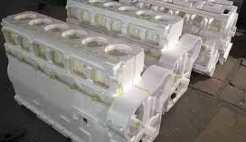
When designing molds for lost foam casting, I focus on several critical aspects to ensure high-quality patterns. For instance, in producing a transmission housing casting for buses—with material HT200, dimensions 463 mm × 500 mm × 350 mm, wall thickness of 8 mm, and mass of 87 kg—the mold must accommodate complex internal cavities. Using a semi-automatic lost foam molding machine, such as the FM-CX-1210 model, I have developed a systematic approach to mold design that covers parting, shrinkage allowances, machining considerations, core-pulling mechanisms, filling methods, wall thickness optimization, venting systems, cooling strategies, mold layout, and auxiliary features. Each of these elements contributes to the efficiency and reliability of the lost foam casting process.
Mold Parting Strategies
In lost foam casting, mold parting is a foundational step that dictates ease of pattern formation and demolding. For simple, regular-shaped castings, I prefer straight parting surfaces along the maximum contour, as this simplifies mold manufacturing and facilitates pattern ejection. However, for complex components with curves, undercuts, or internal features, I often employ stepped parting planes or multi-segment molding, where patterns are formed in sections and later assembled. In the case of the cylindrical transmission housing with hollow structures, I divided the pattern into two halves, A and B, along the plane connecting the centers of three axial holes on the front face. To ensure precise alignment during pattern assembly and prevent mismatches, I incorporated circular locators—convex points on the B-side and matching concave points on the A-side. This design not only eases demolding but also supports automated adhesive application, enhancing consistency in lost foam casting production.
Shrinkage Calculations and Allowances
Accurate shrinkage compensation is vital in lost foam casting to achieve dimensional fidelity. The total shrinkage in the mold must account for both pattern contraction during production and metal solidification shrinkage. For HT200 iron, the liquid metal contraction typically ranges from 0.8% to 1.0%. Pattern shrinkage, influenced by bead type, drying, and aging processes, is determined empirically; with EPS beads, I have measured it to be between 0.3% and 0.5%. Thus, the overall mold shrinkage is calculated as the sum of these factors. Using the formula:
$$ S_{\text{total}} = S_{\text{metal}} + S_{\text{pattern}} $$
where \( S_{\text{metal}} \) is the metal shrinkage rate (e.g., 0.9% for HT200) and \( S_{\text{pattern}} \) is the pattern shrinkage rate (e.g., 0.4% for EPS), the combined shrinkage of 1.3% is applied uniformly across the mold dimensions. This ensures that the final casting meets specifications in lost foam casting applications.
| Component | Shrinkage Rate (%) | Remarks |
|---|---|---|
| Metal (HT200) | 0.8–1.0 | Depends on alloy composition |
| Pattern (EPS Beads) | 0.3–0.5 | Influenced by processing conditions |
| Total Mold Shrinkage | 1.3 | Applied uniformly in design |
Machining Allowances and Draft Angles
To accommodate post-casting machining in lost foam casting, I typically set a uniform machining allowance of 3 mm. For areas prone to dimensional instability or deformation, this allowance can be increased. Draft angles are crucial for smooth pattern ejection; I limit them to a maximum of 1°, but may enhance them in regions where demolding risks distortion. In the transmission housing example, with an overall wall thickness of 8 mm, the B-side features extensive hollow areas. To bolster pattern stability, I added anti-deformation ribs within these cavities. This reinforcement minimizes warping during the lost foam casting process, ensuring geometric accuracy.
Core-Pulling Mechanisms and Movable Inserts
Movable inserts and core-pulling systems are indispensable in lost foam casting for handling complex pattern geometries. Inserts are detachable components that form undercuts, protrusions, or internal features, simplifying mold construction and demolding. During molding, they integrate with the main mold to create a complete cavity; after pattern formation, they are removed separately and reattached for subsequent cycles. To maintain precision, I ensure tight fits and accurate positioning, often using forged aluminum for durability due to frequent handling. Core-pulling mechanisms, such as pneumatic or angled pin systems, automate the extraction of side cores for external undercuts or holes. Pneumatic systems provide high force for long strokes, while angled pin setups use sliders and locking blocks to guide core movement during mold opening. In initial designs for the transmission housing, manual inserts were employed—requiring handling of nine pieces per pattern on the A-side—but this led to high labor intensity, misalignment issues, and flash formation. Transitioning to automated core-pulling mechanisms in subsequent molds reduced manual intervention, increased productivity by 38%, and enhanced consistency in lost foam casting operations.
| Feature | Manual Inserts | Automated Core-Pulling |
|---|---|---|
| Labor Intensity | High | Low |
| Production Efficiency | Moderate | High (38% improvement) |
| Dimensional Accuracy | Prone to errors | Consistent |
| Flash Formation | Common | Minimized |
Filling System Design
The filling system in lost foam casting molds directly impacts pattern quality and cycle times. I design filling ports based on cavity size and shape; for large or intricate molds, multiple ports ensure uniform bead distribution and avoid dead zones. Port location is selected to promote smooth material flow, with dimensions matched to filling speed and volume. In the transmission housing mold, I implemented two filling ports with an internal diameter of 16 mm, using pneumatic automatic guns to inject beads from both ends. This configuration facilitates even cavity filling and eliminates stagnation. Further optimization through pressurized filling reduced filling time by approximately 8 seconds, boosting the efficiency of the lost foam casting process. The relationship between filling time and pressure can be expressed as:
$$ t_f = \frac{V_c}{A_p \cdot v_f} $$
where \( t_f \) is filling time, \( V_c \) is cavity volume, \( A_p \) is port area, and \( v_f \) is filling velocity. By increasing pressure, \( v_f \) rises, thereby decreasing \( t_f \).
Mold Wall Thickness Optimization
Mold wall thickness in lost foam casting balances thermal transfer and structural integrity. I typically maintain walls between 15 mm and 20 mm; thinner walls enhance heat conduction for uniform foaming but may compromise durability, while thicker walls prolong heating and cooling cycles, increasing costs. For localized thick sections in patterns, I adjust wall thickness to improve thermal management. In the transmission housing, the suspension lugs were prone to incomplete cooling and expansion due to their mass. By reducing the mold wall thickness from 17.5 mm to 12.5 mm in these areas, I achieved better heat dissipation, resolving the issue and maintaining the quality standards of lost foam casting. The heat transfer rate can be modeled using Fourier’s law:
$$ q = -k \frac{dT}{dx} $$
where \( q \) is heat flux, \( k \) is thermal conductivity, and \( \frac{dT}{dx} \) is the temperature gradient. Thinner walls increase \( \frac{dT}{dx} \), accelerating heat removal.
Vent (Gas Vent) Design
Vents, or gas vents, are critical in lost foam casting for evacuating gases during bead expansion and fusion. Their diameter and distribution depend on mold size, cavity complexity, and bead characteristics. I avoid overly small diameters to prevent clogging and excessively large ones to deter bead ingress. Vents are spaced evenly across the mold surface, with closer intervals in deep cavities, corners, and protrusions to ensure uniform gas escape and prevent defects like short shots or density variations. However, excessive venting can weaken the mold and raise manufacturing costs. For the transmission housing mold, I used vents with diameters ranging from 4 mm to 10 mm, featuring pin-point orifices of 0.5 mm, positioned within 0.2 mm of the surface. The vent spacing did not exceed 20 mm, with 15 mm in thicker sections, ensuring efficient degassing in the lost foam casting process.
| Parameter | Value | Application Notes |
|---|---|---|
| Vent Diameter | 4–10 mm | Adjust based on bead size |
| Orifice Size | 0.5 mm | Pin-point type for precision |
| Spacing (General) | ≤20 mm | Even distribution |
| Spacing (Thick Sections) | ≤15 mm | Enhanced venting |
Cooling System Implementation
Efficient cooling is essential in lost foam casting to solidify patterns quickly and maintain production rhythm. I primarily use water-cooling systems with internal channels that circulate coolant to absorb heat from the mold. These channels are positioned near the cavity surface for maximum effect, avoiding interference with vents or core mechanisms. Drainage design is crucial; I often employ gravity drainage with sloped ejector plates to guide water to low-point outlets. For improved performance, I integrate vacuum pumps to extract coolant at negative pressures of -0.6 MPa to -0.8 MPa for 15–20 seconds, eliminating water splashing and enhancing the working environment. The cooling efficiency can be quantified by the heat removal rate:
$$ Q = m \cdot c_p \cdot \Delta T $$
where \( Q \) is heat removed, \( m \) is coolant mass flow rate, \( c_p \) is specific heat capacity, and \( \Delta T \) is temperature change. Vacuum-assisted drainage optimizes \( m \), reducing cycle times in lost foam casting.
Mold Layout and Air Chamber Design
Air chambers in lost foam casting molds serve as reservoirs for gas management, working in tandem with vents to regulate cavity pressure during foaming. I design chamber volume proportional to cavity size—larger cavities require more capacity for effective gas displacement—but avoid over-sizing to prevent excessive mold height and thermal inefficiencies. In earlier mold designs, internal cylinders constrained chamber height; by relocating cylinders externally, I reduced chamber height from 100 mm to 75 mm, improving heating and cooling rates without compromising function. This layout refinement supports higher productivity in lost foam casting by streamlining the overall mold structure.
Auxiliary Mechanisms for Automation
To minimize manual handling and pattern damage in lost foam casting, I incorporate auxiliary systems such as automated ejection devices. These include pneumatic suction cups that apply vacuum to lift patterns after demolding, transport them along rails, and release them at designated stations. This simple, cost-effective mechanism reduces deformation and hand marks, enabling one operator to manage multiple machines while upholding quality in lost foam casting production.
Conclusion
In summary, achieving high-quality patterns in lost foam casting hinges on meticulous mold design that addresses parting strategies, shrinkage compensation, core-pulling automation, filling optimization, wall thickness adjustments, venting precision, cooling efficiency, chamber layout, and auxiliary automation. As manufacturing technology advances, I emphasize the importance of integrating automated solutions into mold design for lost foam casting to reduce variability, enhance productivity, and meet the growing demands of industries like automotive and aerospace. Through continuous refinement, lost foam casting remains a robust and efficient method for producing complex metal components.