
In the realm of manufacturing, sand casting remains a cornerstone for producing intricate and high-performance metal parts, particularly for applications requiring robustness and precision. As an engineer specializing in foundry processes, I have dedicated extensive effort to refining sand casting techniques to enhance the quality and efficiency of sand casting products. This article delves into a detailed case study involving the design and optimization of a sand casting process for a rotary disc component, a critical part used in machine tool spindles. The goal is to demonstrate how systematic planning, coupled with numerical simulation, can yield superior sand casting products with minimized defects and improved mechanical properties. Throughout this discussion, the term “sand casting products” will be emphasized to underscore the broader applicability of these methods across various industrial sectors.
The rotary disc, typically fabricated from gray iron such as HT250, demands high dimensional accuracy and surface integrity, especially on its dovetail guide surfaces and large planar faces. These requirements make sand casting an ideal choice due to its flexibility and cost-effectiveness for small to medium batch production. However, achieving defect-free sand casting products necessitates meticulous process design to address challenges like thermal shrinkage, gas entrapment, and filling irregularities. In this work, I present a holistic approach that integrates traditional casting principles with modern simulation tools to optimize every stage—from mold making to solidification control. The insights gained are directly relevant to improving the reliability of sand casting products in demanding applications.
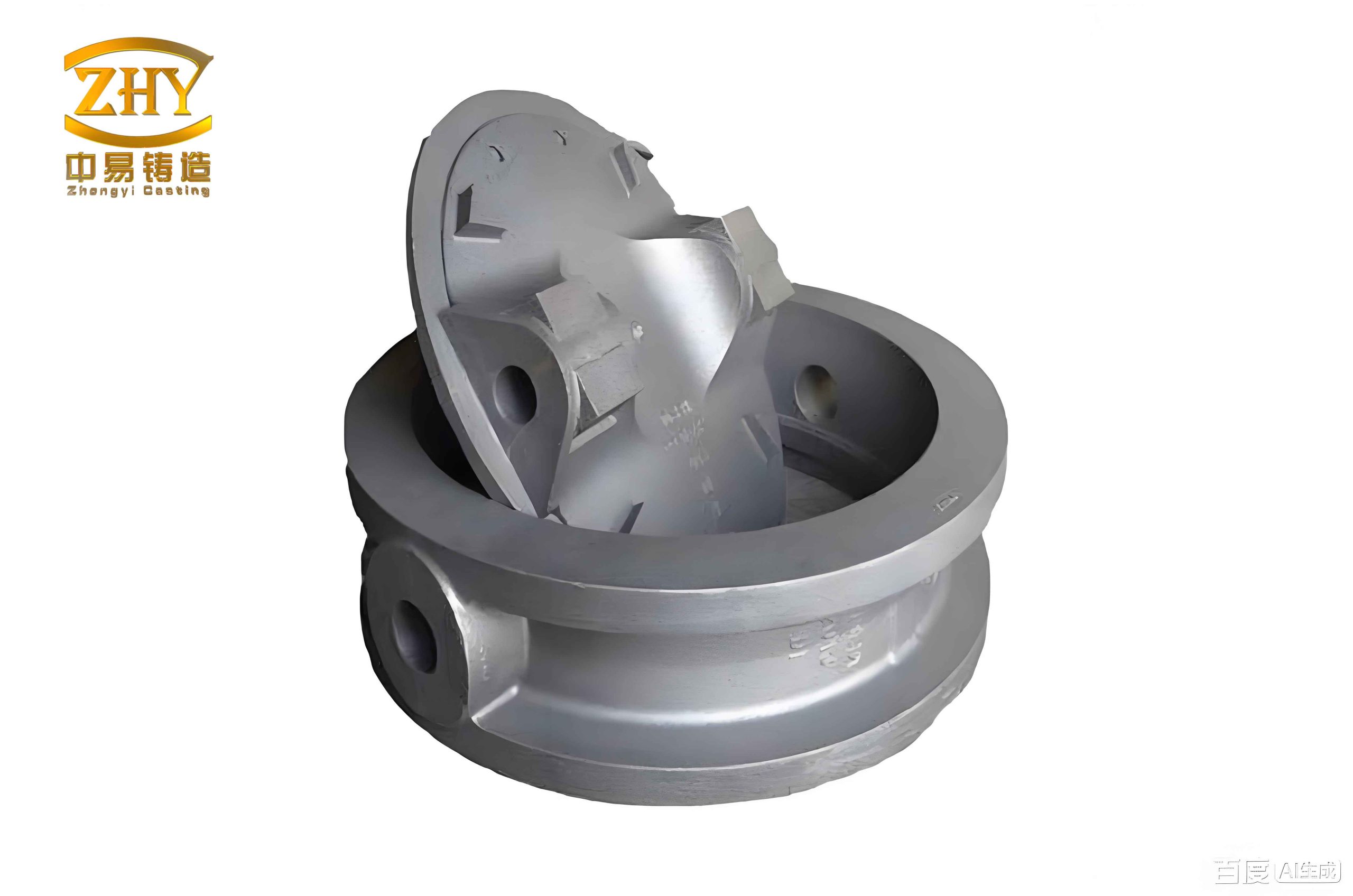
To begin, a thorough structural analysis of the rotary disc is essential. The component features a semi-open internal structure with multiple ribs and holes, as illustrated in the 3D model. Key dimensions include an overall length of 1040 mm, width of 375 mm, and height of 158 mm, classifying it as a medium-sized, thin-walled casting. Wall thickness varies from 10 mm to 30 mm, with the minimum hole diameter being 6 mm. Such geometry introduces complexities in mold filling and solidification, potentially leading to defects like shrinkage porosity or cold shuts if not properly managed. The critical quality zones are the dovetail guide surfaces and bolt hole faces, which must remain free of imperfections to ensure functionality. Table 1 summarizes the primary structural parameters, highlighting the challenges inherent in producing such sand casting products.
| Parameter | Value | Significance |
|---|---|---|
| Overall Dimensions | 1040 mm × 375 mm × 158 mm | Determines mold size and pouring volume |
| Wall Thickness Range | 10 mm to 30 mm | Affects cooling rates and defect formation |
| Minimum Hole Diameter | 6 mm | Poses challenges for core making and venting |
| Critical Surfaces | Dovetail guide and large plane | Require high integrity for machining and service |
Based on this analysis, the casting material selected is HT250 gray iron, known for its excellent castability, good wear resistance, and vibration damping properties. These characteristics are vital for sand casting products subjected to dynamic loads. The casting process employs furan resin no-bake sand for both molds and cores, which offers high dimensional accuracy and smooth surface finish. For small-batch production, manual molding and core assembly are utilized, with alcohol-based coatings applied to enhance surface quality. Dimensional tolerances are set to CT11, mass tolerances to MT10, and weight tolerances to ±4%, adhering to industry standards for sand casting products. The linear shrinkage allowance is determined as 0.9%, accounting for restricted contraction during solidification. Machining allowances are allocated strategically: 5 mm for guide sides, 8 mm for end faces, 10 mm for top surfaces, and 5 mm for other areas, ensuring sufficient material for post-casting operations.
The cornerstone of successful sand casting lies in the strategic selection of pouring position and parting plane. For the rotary disc, I opted to orient the casting with the large planar face upward and the dovetail guide surface downward. This orientation leverages gravity to enhance filling of thin sections and promotes directional solidification from the bottom upward, thereby improving the metallurgical quality of critical surfaces. The parting plane is placed at the largest cross-section—the large plane—simplifying mold separation, pattern withdrawal, and core placement. This configuration also facilitates the use of an open riser at the highest point of the inclined pouring setup to aid slag collection and gas evacuation. Such decisions are pivotal in minimizing defects in sand casting products, as they directly influence thermal gradients and liquid metal flow.
To quantify the benefits of this orientation, consider the pressure gradient established during inclined pouring. When the mold is tilted at an angle θ (e.g., 10°), the metallostatic pressure at any point along the casting height can be expressed as:
$$ P(h) = \rho g h \sin(\theta) $$
where \( P(h) \) is the pressure at height \( h \), \( \rho \) is the molten iron density (approximately 7100 kg/m³ for HT250), \( g \) is gravitational acceleration, and \( \theta \) is the tilt angle. This pressure gradient promotes feeding and reduces shrinkage porosity, particularly in thicker sections. Moreover, the filling time \( t_f \) can be estimated using empirical formulas tailored for sand casting products:
$$ t_f = k \sqrt{W} $$
where \( W \) is the casting weight (174.45 kg in this case) and \( k \) is a coefficient dependent on gating design (typically 0.8 to 1.2 for iron castings). For this component, \( t_f \) is optimized to around 20-25 seconds to ensure smooth filling without turbulence.
The gating system design is another critical aspect. I implemented a stepped gating approach combined with inclined pouring, where inner gates are located at both the bottom and top surfaces on one end of the casting length. This dual-level introduction of molten metal ensures sequential filling: initially from the bottom gate to minimize splash and oxidation, followed by the top gate as the metal level rises. This promotes temperature stratification and reduces thermal stress in the lower regions, crucial for maintaining the integrity of the dovetail guides. The gating ratio (sprue:runner:gate) is calibrated to 1:2:1.5 to balance flow velocity and pressure, preventing mold erosion and gas entrainment. Table 2 outlines the key gating system parameters, which are derived from iterative simulations and historical data for similar sand casting products.
| Parameter | Value | Function |
|---|---|---|
| Pouring Temperature | 1380-1400°C | Ensures proper fluidity and reduces shrinkage |
| Gating Ratio | 1:2:1.5 (Sprue:Runner:Gate) | Controls flow rate and minimizes turbulence |
| Number of Gates | 2 (Bottom and Top) | Facilitates stepped filling and temperature management |
| Gate Dimensions | 20 mm × 15 mm (each) | Optimized for metal delivery and easy removal |
Riser and chill design are employed to further control solidification. Three open risers are positioned at the highest points of the casting to collect slag and provide a pressure head for feeding. Their volume is determined based on the modulus method, ensuring they solidify after the casting to compensate for shrinkage. For local hot spots, particularly near thicker sections like bolt holes, iron chills are inserted to accelerate cooling and refine grain structure. The effectiveness of chills can be modeled using Fourier’s law of heat conduction:
$$ q = -k_c \frac{dT}{dx} $$
where \( q \) is heat flux, \( k_c \) is thermal conductivity of the chill material, and \( \frac{dT}{dx} \) is the temperature gradient. By placing chills strategically, the solidification time \( t_s \) in critical zones is reduced, which enhances mechanical properties and minimizes porosity. This holistic approach ensures that sand casting products like the rotary disc achieve uniform microstructure and high durability.
Numerical simulation plays an indispensable role in validating and refining the casting process. Using AnyCasting software, I conducted extensive simulations of filling and solidification sequences. The initial scheme involved a bottom-gated inclined pouring system, which showed favorable filling patterns but indicated potential shrinkage defects in upper thick sections. Probability defect parameters, derived from residual melt volume analysis, highlighted risk areas with values exceeding 0.6 (on a scale of 0 to 1), necessitating optimization. The first optimization introduced stepped gating and additional risers, which improved temperature distribution and reduced defect probabilities. However, simulations still revealed hot spots near bolt holes, leading to the second optimization with chills. The final simulation results demonstrated a significant reduction in defect indicators, with probabilities below 0.2 in critical zones, confirming the efficacy of the design. Table 3 compares the simulation outcomes across different stages, illustrating the progressive enhancement in quality for sand casting products.
| Scheme | Filling Time (s) | Max Defect Probability | Solidification Time (s) | Key Improvements |
|---|---|---|---|---|
| Initial (Bottom Gating) | 22.5 | 0.85 | 1252.8 | Steady filling but high shrinkage risk |
| First Optimization (Stepped Gating) | 24.1 | 0.45 | 1224.0 | Better temperature gradient, reduced defects |
| Second Optimization (With Chills) | 23.8 | 0.18 | 1176.6 | Eliminated hot spots, uniform solidification |
The core design for the rotary disc is equally vital, given its internal cavities and ribs. I developed a composite core system consisting of a main core and multiple small insert cores. The main core is reinforced with a tubular core frame made from hollow steel pipes arranged in a triangular pattern. This frame provides structural integrity during handling and pouring, while perforations in the pipes serve as vents to exhaust gases generated during casting. The core assembly process involves bonding small insert cores to the main core using adhesives and steel pins for alignment. This modular approach simplifies manufacturing and ensures dimensional accuracy, which is paramount for complex sand casting products. The core dimensions are calculated with allowances for thermal expansion, using the formula:
$$ L_c = L_0 (1 + \alpha \Delta T) $$
where \( L_c \) is the core length at pouring temperature, \( L_0 \) is the room-temperature length, \( \alpha \) is the thermal expansion coefficient of the sand mixture (approximately 0.0012/°C for furan resin sand), and \( \Delta T \) is the temperature rise. Proper venting capacity is ensured by designing vent channels with cross-sectional areas equal to 20-30% of the total gate area, preventing backpressure and gas-related defects.
To evaluate the overall process efficiency, the casting yield is computed. The yield, a key metric for economic production of sand casting products, is defined as the ratio of casting weight to total poured weight. For this rotary disc:
$$ \text{Casting Yield} = \frac{W_c}{W_c + W_g + W_r} \times 100\% $$
where \( W_c = 174.45 \, \text{kg} \) (casting weight), \( W_g = 85.25 \, \text{kg} \) (gating system weight), and \( W_r = 9.8 \, \text{kg} \) (riser weight). Substituting the values:
$$ \text{Casting Yield} = \frac{174.45}{174.45 + 85.25 + 9.8} \times 100\% = 64.73\% $$
This yield is considered high for complex sand casting products, indicating minimal waste and cost-effectiveness. Additionally, the process reduces post-casting machining by ensuring sound surfaces on critical areas, further lowering production expenses.
In conclusion, the sand casting process designed for the rotary disc component exemplifies how integrated design and simulation can yield high-quality sand casting products. By optimizing pouring orientation, gating, risering, and cooling techniques, defects are minimized, and mechanical properties are enhanced. The use of numerical simulation allows for predictive analysis and iterative refinement, reducing trial-and-error in foundry operations. This methodology is broadly applicable to other sand casting products, especially those with intricate geometries and stringent quality requirements. Future work could explore advanced materials like ductile iron or aluminum alloys, extending these principles to a wider range of applications. Ultimately, the continuous improvement of sand casting processes remains essential for meeting the evolving demands of modern manufacturing, ensuring that sand casting products deliver reliability and performance in critical engineering systems.
The successful implementation of this process underscores the importance of a systematic approach in foundry engineering. From initial structural assessment to final simulation validation, each step contributes to the overall quality of sand casting products. By sharing these insights, I aim to foster innovation and excellence in the production of sand casting products across industries, from automotive to machinery. As technology advances, integrating artificial intelligence and real-time monitoring could further optimize these processes, paving the way for smarter and more efficient manufacturing of sand casting products.