
In the field of advanced manufacturing, lost foam casting has emerged as a clean and efficient casting process, widely applied in industries such as aerospace and automotive. However, traditional design methods for lost foam casting often rely heavily on designer experience, leading to issues like prolonged design cycles, difficulty in precision control, and insufficient scheme optimization. With the rapid development of computer technology, integrating CAD/CAE technologies into lost foam casting design has become a crucial pathway to enhance design capabilities. In this work, we propose a comprehensive computer-aided design solution aimed at addressing these challenges through parameterized modeling, finite element analysis, and intelligent optimization. Our approach leverages specialized software platforms and integrated databases to significantly improve design efficiency and quality. Throughout this article, we will delve into the technical details of implementing and optimizing computer-aided design for lost foam casting, emphasizing the role of digital tools in revolutionizing this process.
The core of our methodology revolves around a multi-layered CAD system framework specifically tailored for lost foam casting. We developed a system based on a multi-tier architecture, comprising presentation, business logic, and data layers. The presentation layer is built on a CATIA secondary development platform using MFC frameworks, enabling visual operations for parameterized modeling and model editing. The business logic layer includes a geometry modeling engine, process calculation modules, and optimization analysis modules. The geometry modeling engine, developed on the CATIA CAA platform, handles feature modeling and assembly design. Process calculation modules, programmed in C++, implement algorithms for gating system design and cooling system layout. The optimization analysis module integrates ANSYS finite element analysis interfaces through secondary development, automating tasks like model import/export, meshing, and solving. The data layer uses SQL Server databases to store structured data such as process parameters and model features, while a file system manages unstructured data like 3D models and analysis results. This architecture ensures system stability and scalability through standard interfaces for data exchange and function calls.
To provide a clear overview of the system’s functionality, we divided it into six main modules, as summarized in the table below. These modules cover all aspects of lost foam casting design, from model creation to data management.
| Module | Sub-modules | Key Functions |
|---|---|---|
| Model Design Module | Lost foam model library, assembly design tools, parameterized design tools | Rapid construction and modification of models; includes standard models ranging from 50 to 500 mm |
| Process Design Module | Gating system designer, cooling system layout tool, process parameter calculator | Automatic generation of recommended process schemes based on part features |
| Analysis Optimization Module | Model meshing tools, stress-strain analysis, temperature field analysis, structural optimization | Supports tetrahedral and hexahedral meshing; integrates finite element analysis for optimization |
| Data Management Module | Engineering drawing management, model version control, process parameter management | Maintains data integrity and version history for projects |
| System Management Module | User permission management, operation log recording, system configuration | Provides foundational security and administrative functions |
| Auxiliary Tools Module | Dimension checking, interference detection, engineering drawing generation | Offers practical utilities for design validation and documentation |
The data flow within the system is designed using an object-oriented approach to create a seamless processing chain. Initially, basic parameters such as product type, dimensions, and accuracy requirements are input via the user interface, validated, and stored in the SQL Server database. The system then invokes the parameterized modeling module to automatically generate 3D models based on product parameters. Model data is saved in CATIA native format (.CATPart), with key feature parameters extracted and stored in the database. During the process design stage, the system retrieves matching process parameters from the knowledge base, calculates specific process dimensions based on model features, and generates process scheme files in XML format. In the optimization analysis stage, model data is converted to ANSYS-compatible formats (.igs) for finite element analysis, with results saved as HTML reports and linked to project files. Final design schemes include various file formats like 3D models, engineering drawings, and analysis reports, all managed by a project management module for version control and access permissions. Multiple checkpoints are integrated into the data flow to ensure data completeness and consistency, which is critical for reliable lost foam casting design.
In lost foam casting, three-dimensional parameterized modeling is a cornerstone for efficient design. We employ a feature-based hybrid modeling strategy, starting with the construction of benchmark features to generate the base body through operations like sweeping or rotation. For instance, in a cylindrical lost foam model, the base diameter D and height H must satisfy geometric constraints to ensure molding quality, with the D/H ratio typically ranging from 0.5 to 2.0. After generating the base body, functional features such as gates and cooling channels are added via Boolean operations. The cross-sectional area A of the gate is related to the model volume V to meet feeding requirements, as expressed by the formula:
$$A = K \left( \frac{V}{h} \right)^{\frac{1}{2}}$$
where K is the feeding coefficient (generally between 0.7 and 1.2), and h is the static head height of the molten metal. In practical modeling, we first determine base dimensions, then calculate gate area using this formula, and generate uniformly distributed gating systems through feature arrays. For complex surfaces, spline modeling methods are used, adjusting surface shapes via control points for precise local feature control. During modeling, features are constrained by parent-child relationships to ensure associativity during updates.
Parameter association design is implemented through a CATIA secondary development platform, establishing a parameterized design framework. We define parameter expressions including model dimensions (e.g., wall thickness t, fillet radius r), position parameters (e.g., feature array spacing s, relative coordinates x, y, z), and process parameters (e.g., shrinkage rate α, machining allowance δ). The relationship between wall thickness and model dimensions is given by:
$$t = \beta (LWH)^{\frac{1}{3}} + C$$
where β is the process coefficient (ranging from 0.08 to 0.12), L, W, and H are the length, width, and height of the model, respectively, and C is the base wall thickness (usually 3–5 mm). A parameter associator is programmed in VB.NET to link geometric and process parameters. For example, when modifying base dimensions, the system automatically updates related parameters like wall thickness and gate sizes. A constraint manager ensures design rules are not violated during parameter changes. For complex structures, parameter group management enables batch adjustments.
Model verification and inspection are crucial in lost foam casting to ensure design accuracy. We establish a multi-level verification system, starting with geometric consistency checks including topological integrity and surface continuity. For cavity structures, numerical simulation validates ventilation performance, with the filling time t calculated as:
$$t = \mu \left( \rho g h \right)^{-\frac{1}{2}} \frac{L^2}{S}$$
where μ is the sand permeability coefficient, ρ is the molten metal density, g is gravitational acceleration, h is the static head height, L is the flow length, and S is the cavity cross-sectional area. Theoretical filling times from this formula are compared with simulation results for verification. Wall thickness uniformity is also checked, with differences between adjacent walls not exceeding 20%. For critical dimensions, tolerance bands are set for automatic inspection, with out-of-tolerance parts automatically annotated. A check report generator outputs results in HTML format, including geometric parameter tables, inspection item lists, and issue descriptions, supporting remote collaborative review. After inspection, models are archived via a PDM system, recording design versions and modification history.
The construction of a process database and knowledge base is integral to optimizing lost foam casting design. We use SQL Server 2019 to build the process database, designing four key data tables: the main process parameter table (recording core parameters like pouring temperature from 600–750°C and solidification time from 3–30 s), material property table (storing physical performance data of foam types like EPS20 and EPS30), mold structure table (containing 3D models of standard gating systems), and process rule table (storing design specifications and empirical data). Knowledge acquisition involves field research in lost foam casting enterprises, where expert insights from senior engineers are recorded, such as design rules for large thin-walled parts. A management system based on a B/S architecture is developed using Vue and SpringBoot, providing template-based knowledge entry interfaces and supporting uploads of multimedia content like CAD drawings and process photos. The data retrieval module integrates Elasticsearch for precise queries by part type or size range. For instance, when designers create thin-walled structures, the system automatically pushes relevant process suggestions. Usage frequency of knowledge entries is tracked weekly to generate value assessment reports, guiding continuous database optimization for lost foam casting applications.
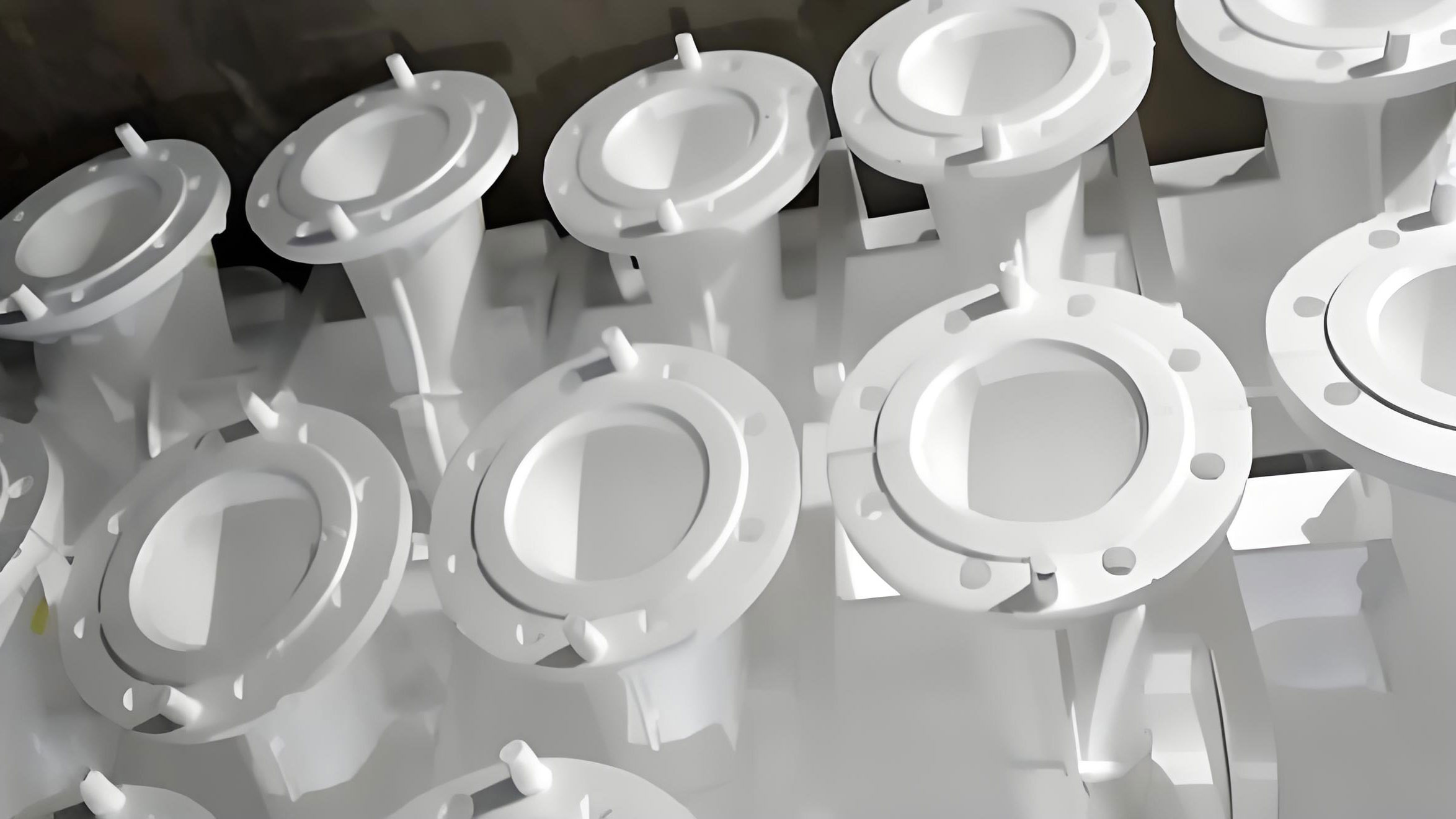
Based on finite element analysis, structural optimization plays a pivotal role in enhancing lost foam casting designs. We establish a mechanical model for a case study on an engine block lost foam, considering the composite effects of molten metal static pressure and thermal stress during pouring. A thermal-mechanical coupling analysis is employed in ANSYS Workbench. First, the model in STEP format is imported, with material properties set for the EPS model: density of 20 kg/m³, elastic modulus of 3.5 MPa, Poisson’s ratio of 0.3, and thermal conductivity of 0.034 W/(m·K). For molten metal pressure loads, the pressure distribution is derived from Bernoulli’s equation:
$$p(h) = \rho g h + \frac{\rho v^2}{2} + p_0$$
where p(h) is the pressure at depth h, ρ is the molten metal density (7,200 kg/m³), g is gravitational acceleration, v is the pouring speed (0.5 m/s), and p₀ is atmospheric pressure. In calculations, the cavity is divided into five layers, each with corresponding pressure loads. The temperature field uses transient thermal analysis, with initial molten metal temperature at 720°C, model initial temperature at 30°C, and ambient temperature at 25°C, simulating cooling through heat transfer coefficients. Monitoring points at critical structures (e.g., water jacket walls, oil passages) record stress and deformation data.
Meshing and boundary condition settings are tailored to model features. For regular regions like outer walls and bases, hexahedral meshes with an element size of 8 mm are used; for complex surfaces like water jacket turns, tetrahedral meshes are applied with local refinement in high-curvature areas, minimizing element size to 2 mm. Mesh quality is checked via Mesh Metrics tools, ensuring orthogonal quality above 0.7 and skewness below 0.8. The actual meshing results include 85,642 total elements and 156,328 nodes. Boundary conditions involve fixed constraints at the model bottom to restrict all degrees of freedom. On molten metal contact surfaces, the calculated pressure loads are applied with convective heat transfer boundaries (coefficient of 5,000 W/(m²·K)). External surfaces have natural convection boundaries (coefficient of 20 W/(m²·K)), and gate inlets set molten metal at 720°C with temperature-time curves defining cooling. Nonlinear contacts are configured via APDL commands with a friction coefficient of 0.3. The temperature-time curve for the lost foam casting pouring and cooling process illustrates the thermal dynamics, showing temperature drops from 720°C to ambient levels over time, which is vital for predicting solidification behavior in lost foam casting.
For optimization, we combine response surface methodology and genetic algorithms to achieve multi-objective optimization, minimizing deformation while ensuring strength. The implementation steps include defining design variables such as rib thickness (4–8 mm), rib spacing (40–80 mm), and fillet radius (2–5 mm), totaling six parameters. A parametric model is established in ANSYS Workbench’s parameter manager, with APDL scripts enabling automatic updates. Fifty experimental points are designed for finite element analysis to obtain response values (maximum deformation and stress). A quadratic polynomial builds the response surface model, achieving a correlation coefficient above 0.95. Genetic algorithm parameters are set: population size of 50, crossover probability of 0.8, mutation probability of 0.1, and 100 iterations. Optimization targets are maximum deformation below 0.5 mm and maximum stress below 2 MPa. The algorithm is implemented in Matlab, interacting with ANSYS via file exchanges. After 78 iterations, an optimal solution is obtained: rib thickness of 6 mm, spacing of 55 mm, and fillet radius of 3 mm, resulting in maximum deformation of 0.43 mm and maximum stress of 1.82 MPa, representing reductions of 18% and 15% compared to the initial scheme, respectively. This optimization directly benefits lost foam casting by improving mold durability and casting quality.
System implementation and application validation demonstrate the practical impact of our computer-aided design approach in lost foam casting. Core functional modules are realized using a plugin architecture. The model design module, based on CATIA CAA development, enables parameterized modeling for 50 standard lost foam types. The process design module uses a C++-written calculation engine with 200 built-in process parameter templates. The analysis optimization module leverages ANSYS secondary development interfaces for automatic meshing and result analysis. The data management module employs a distributed architecture, with SQL Server for structured data and MongoDB for CAD model files. The knowledge base module, built on Elasticsearch, supports full-text retrieval for rapid access to process knowledge. System modules communicate via Web Service interfaces with token authentication for security.
To validate effectiveness, we applied the system to three typical parts from an engine manufacturer: a cylinder block (large complex part), a connecting rod (medium precision part), and a bracket (small thin-walled part). By comparing design outcomes before and after system use, we assessed improvements in efficiency, quality, and cost control. The results are summarized in the table below, highlighting the advantages of computer-aided design in lost foam casting.
| Evaluation Metric | Part Type | Traditional Method | System Design | Improvement Effect |
|---|---|---|---|---|
| Design Cycle (days) | Cylinder Block | 15 | 8 | -46.7% |
| Connecting Rod | 8 | 4 | -50.0% | |
| Bracket | 5 | 2 | -60.0% | |
| Scheme Revisions (times) | Cylinder Block | 6 | 2 | -66.7% |
| Connecting Rod | 4 | 1 | -75.0% | |
| Bracket | 3 | 1 | -66.7% | |
| Rejection Rate (%) | Cylinder Block | 8.5 | 3.2 | -62.4% |
| Connecting Rod | 6.8 | 2.5 | -63.2% | |
| Bracket | 5.2 | 1.8 | -65.4% |
These results underscore the transformative potential of computer-aided design in lost foam casting, with design cycles shortened by up to 60%, revision counts reduced by up to 75%, and rejection rates lowered by over 60%. Such improvements not only enhance productivity but also reduce material waste and costs, making lost foam casting more competitive in high-precision manufacturing sectors.
In conclusion, our research on computer-aided design in lost foam casting establishes a comprehensive design optimization scheme that integrates parameterized modeling, intelligent optimization, and process management. By leveraging advanced CAD/CAE technologies, we have developed a system that addresses key challenges in lost foam casting, such as inefficiency and precision control. The implementation of a multi-layered architecture, coupled with robust databases and finite element analysis, has proven effective in real-world applications, as validated through case studies on engine components. Future work will focus on refining optimization algorithms, expanding system functionalities, and enhancing design intelligence to further advance the digital transformation of lost foam casting. This ongoing effort aims to push the boundaries of what is possible in casting technology, ensuring that lost foam casting remains at the forefront of innovative manufacturing processes.
The integration of computer-aided design into lost foam casting not only streamlines workflows but also enables more sustainable practices by minimizing errors and resource consumption. As industries continue to demand higher quality and faster turnaround times, solutions like ours provide a scalable framework for adopting digital tools in traditional manufacturing. We believe that the principles outlined here can be extended to other casting methods, fostering broader advancements in the field. Through continuous iteration and collaboration with industry partners, we aim to set new standards for efficiency and accuracy in lost foam casting, ultimately contributing to the evolution of smart manufacturing ecosystems worldwide.