
In our foundry, we utilize the lost foam casting (LFC) process for producing complex components like reducer housings, prized for its ability to deliver castings with excellent dimensional accuracy, superior surface finish, and high yield. The material of choice for these demanding applications is often spheroidal graphite cast iron (ductile iron), specifically grade QT450-10, which offers an optimal balance of strength, toughness, and wear resistance. However, transitioning this alloy to the LFC environment presented us with significant challenges in the form of persistent inclusion and shrinkage cavity defects. This document details our first-hand investigation, root cause analysis, and the development of innovative, practical solutions to eliminate these defects, ensuring the reliable production of high-integrity spheroidal graphite cast iron castings.
The reducer housing in question is a substantial component, weighing approximately 112 kg with wall thicknesses ranging from 14 mm to 54 mm. This variation inevitably creates pronounced geometric hot spots, particularly around boss and rib intersections. Our initial process setup followed conventional LFC wisdom for spheroidal graphite cast iron. We employed a copolymer bead (STMMA) for the foam pattern to balance gas generation and carbon residue. The gating system was designed with a pouring cup, sprue, runner, and ingates. Key process parameters were set as follows:
| Process Parameter | Value / Range |
|---|---|
| Pouring Temperature | 1370 – 1440 °C |
| Tapping Temperature | 1580 – 1600 °C |
| Mould Negative Pressure | -0.04 to -0.06 MPa |
| Pressure Holding Time | 900 s |
The chemical composition was meticulously controlled to meet the QT450-10 specification, as summarized below:
| Element | wt.% |
|---|---|
| C | 3.5 – 4.0 |
| Si | 2.0 – 3.0 |
| Mn | ≤ 0.45 |
| P | ≤ 0.05 |
| S | ≤ 0.025 |
| Mg | 0.02 – 0.06 |
| RE | 0.015 – 0.040 |
Despite achieving satisfactory mechanical properties and nodularity (2-3 grade) on separately cast Y-blocks, the initial production runs of the actual housing were plagued by defects. Two primary issues emerged: (1) Non-metallic inclusions, predominantly on the upper vertical faces of the casting, and (2) Shrinkage cavities in the thickest sections, specifically around bolt boss areas.
Deconstructing the Defects: A Root Cause Analysis
The Inevitability of Inclusions in LFC for Spheroidal Graphite Cast Iron
The formation of inclusions is intrinsically linked to the thermal degradation of the foam pattern. Unlike traditional casting, the metal displaces and vaporizes a solid polymer. For common LFC materials like EPS (Expanded Polystyrene) and STMMA, the pyrolysis reactions are:
For EPS:
$$ C_8H_8(s) \xrightarrow{\Delta} 8C(s) + 4H_2(g) $$
For STMMA (approximated):
$$ C_xH_yO_z(s) \xrightarrow{\Delta} aC(s) + bCO_2(g) + cH_2(g) + \text{other hydrocarbons} $$
The key point is the co-production of solid carbon (soot) and gaseous products. The high carbon content of spheroidal graphite cast iron (3.5-3.8%) further exacerbates the tendency for carbonaceous defects. During pouring, the advancing metal front thermally decomposes the foam. If the resulting gaseous and liquid pyrolysis products are not completely evacuated through the coating and sand, or if the metal front is unstable, the solid carbon residues can become entrapped at the metal front, particularly on upward-facing surfaces. This results in the observed subsurface inclusions. We conducted a machining test to determine the depth of these defects, which consistently measured less than 8 mm from the surface.
The Genesis of Shrinkage Cavities in Ductile Iron
Shrinkage defects in spheroidal graphite cast iron are fundamentally a feeding problem during the liquid-to-solid phase change. Ductile iron exhibits significant graphite expansion during eutectic solidification, but this expansion is often insufficient to compensate for the liquid shrinkage in isolated hot spots, especially in heavier sections where mushy zone feeding is difficult. The localized solidification sequence in a hot spot can be modeled by considering the thermal modulus. The solidification time \( t_f \) for a section is related to its modulus \( M \) (Volume/Surface Area ratio):
$$ t_f \propto M^n $$
where \( n \) is a constant (typically ~2). A larger \( M \) in a hot spot leads to prolonged solidification, creating a “thermal center” that is last to freeze and cannot be fed by surrounding solidified metal, resulting in a macroscopic shrinkage cavity.
In our initial process, neither the gating system nor the mold environment provided adequate directional solidification or local cooling to mitigate these hot spots inherent in the housing’s design. Traditional solutions like risers or internal chills were deemed problematic for LFC: risers lower yield and complicate the foam cluster, while rigid chills are difficult to secure during compaction and can cause dimensional inaccuracies or sand collapse.
Innovative Solutions and Rigorous Validation
Strategy 1: Managing Inclusions via Strategic Machining Allowance
Recognizing that the complete elimination of carbonaceous inclusions in LFC for spheroidal graphite cast iron is nearly impossible, we adopted a pragmatic containment strategy. Since the defect depth was quantified to be ≤ 8 mm, the solution was straightforward: increase the machining allowance on all critical vertical faces from the original 4 mm to a new standard of 8 mm. This additional material provides a “sacrificial layer” that is removed during machining, guaranteeing a clean, defect-free final surface. The effectiveness of this simple modification was profound, as evidenced by the yield data from batch production:
| Process Stage | Machining Yield Rate |
|---|---|
| Before Modification (4 mm allowance) | ~88% |
| After Modification (8 mm allowance) | ~97.96% |
This significant improvement confirmed that managing, rather than utterly preventing, inclusion entrapment was a viable and highly effective strategy for this component.
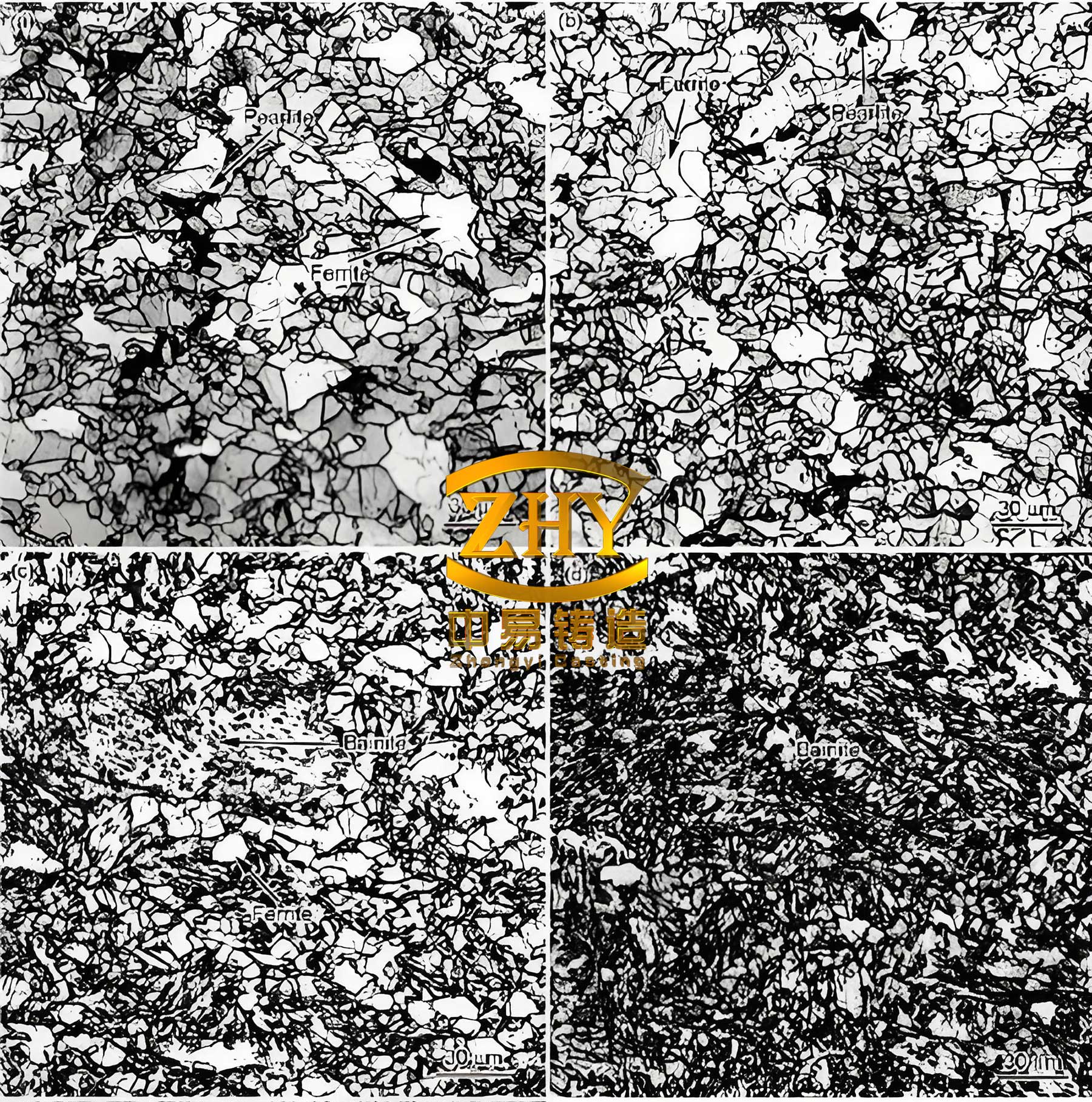
The success of our process modifications ultimately relies on achieving the correct metallurgical structure. A sound spheroidal graphite cast iron microstructure, free from shrinkage or carbides, is the foundation for the required mechanical properties. The spherical graphite nodules, embedded in a ferritic or pearlitic matrix, are clearly visible and are the key to the material’s ductility and strength.
Strategy 2: Eliminating Shrinkage with Novel Cooling Techniques
Addressing the shrinkage cavities required a fundamental change in the thermal dynamics at the hot spots. We developed and validated two novel techniques tailored for the LFC process: the Heat Dissipation Fin (HDF) and the Flexible Chill.
A. The Heat Dissipation Fin (HDF) Process
This was our primary and most successful innovation. The core principle is to artificially increase the surface area and enhance convective cooling at the geometric hot spot. We attached specially shaped foam blocks, or “fins,” directly onto the foam pattern at the identified shrinkage-prone locations (e.g., bolt bosses). The modified cluster is then coated, dried, and cast as usual.
Mechanism of Action: During pouring and the critical solidification period, the negative pressure system is active (-0.04 to -0.06 MPa). This continuously draws cooler ambient air from the top of the flask down through the permeable sand. This airflow performs two crucial functions at the HDF site:
- Increased Surface Area: The fin increases the effective surface area (\(A\)) of the hot spot. According to Newton’s law of cooling, the convective heat transfer rate \( \dot{Q}_{conv} \) is:
$$ \dot{Q}_{conv} = h A (T_{surface} – T_{air}) $$
where \( h \) is the convective heat transfer coefficient. Increasing \(A\) directly increases the heat extraction rate. - Enhanced Convective Cooling: The flowing air creates a micro-channel cooling effect around the fin and the adjacent sand, significantly increasing the local \(h\) and carrying away latent heat. This combined effect drastically reduces the local solidification time \( t_f \), effectively reducing the thermal modulus of the hot spot and transforming the solidification mode from a mushy, isolated center to a directional one.
Implementation & Results: For the problematic bolt boss, we attached twelve foam fins (approx. 50 x 30 x 7 mm each). No other changes were made to the chemistry or major pouring parameters. Post-casting and machining inspection revealed perfectly sound boss sections, completely free of shrinkage. A batch production of over 2,000 housings confirmed the robustness and repeatability of the HDF process.
B. The Flexible Chill Process
As an alternative, we explored a method to introduce a traditional chilling effect without the handling difficulties of solid chills. In this process, steel shot (1-3 mm diameter) is placed into a small cavity or against the pattern at the hot spot location. The area is then sealed with high-temperature resistant tape to prevent the shot from dispersing during sand compaction and filling.
Mechanism of Action: The mass of steel shot acts as a high-thermal-capacity, conformable chill. Upon metal entry, the heat is rapidly absorbed by the shot:
$$ Q_{absorbed} = m_{shot} \cdot c_{p, steel} \cdot \Delta T_{shot} $$
where \( m_{shot} \) is the mass of the shot, \( c_{p, steel} \) is its specific heat capacity, and \( \Delta T \) is its temperature rise. This rapid heat extraction creates a strong directional solidification gradient away from the hot spot. The “flexible” nature allows it to conform to complex surfaces and remain in place during vibration.
While effective in trial runs, this method was found to be more operator-sensitive than the HDF process, requiring careful control of shot quantity and secure sealing. It is best suited for locations where attaching a foam fin is geometrically challenging.
The comparative advantages of our developed methods over traditional approaches are summarized below:
| Solution Method | Mechanism | Advantages for LFC | Disadvantages/Limitations |
|---|---|---|---|
| Heat Dissipation Fin (HDF) | Enhances convective cooling via increased surface area and negative pressure airflow. | Simple to glue to pattern; negligible cost; very high casting yield; easy fettling. | Requires accessible surface for fin attachment. |
| Flexible Chill | Provides massive chilling via conformable steel shot heat sink. | Effective for deep/concave hot spots; strong chilling power. | Process complexity (placement, sealing); potential for movement; added cost. |
| Traditional Riser | Provides liquid metal feed reservoir. | Well-understood principle. | Lowers process yield; complicates cluster assembly and coating; increased cleaning cost. |
| Solid Cast Iron Chill | Provides conductive cooling. | Strong, predictable chilling. | Difficult to fix in LFC mold; risk of sand collapse; can cause dimensional issues. |
Conclusion and Foundry Perspective
Through systematic investigation and innovative thinking, we successfully resolved the major quality barriers in producing spheroidal graphite cast iron reducer housings via the lost foam process. Our work underscores several key principles for foundry engineers:
- Inclusion Management is Key: For carbon-sensitive alloys like spheroidal graphite cast iron in LFC, a strategy based on quantified defect depth and strategic machining allowance is often more practical and reliable than attempting absolute prevention.
- Harnessing Process Physics: The HDF process is a elegant example of leveraging the inherent characteristics of the LFC system—specifically the continuous through-sand airflow during negative pressure application—to solve a classic foundry problem (shrinkage). It transforms a potential weakness (pattern gasification) into a strength (active cooling).
- Practicality Over Purity: Both the HDF and Flexible Chill methods prioritize shop-floor practicality, high yield, and simplicity over theoretically perfect but cumbersome solutions. They integrate seamlessly into existing LFC workflow.
- Holistic Parameter Control: While these new techniques were pivotal, their success was underpinned by strict control of baseline parameters: consistent foam material (STMMA), precise coating permeability, stable pouring temperature, and maintained negative pressure throughout solidification.
This study demonstrates that the challenges of casting complex spheroidal graphite cast iron components via lost foam are surmountable. By understanding the root causes of defects and developing process-specific solutions, we have established a robust, high-yield production route that leverages the full benefits of the lost foam technique for high-performance ductile iron castings.