
In the vast landscape of industrial manufacturing, steel castings form an indispensable backbone. As a professional deeply involved in foundry operations for decades, I have witnessed firsthand the critical role that steel castings, particularly those for components like butterfly valves, play in national economic development and infrastructure. These valves, with their diverse types such as gate, globe, ball, and check valves, are ubiquitous. However, the production of steel castings for butterfly valve bodies and discs is fraught with challenges, primarily stemming from defects like shrinkage cavities and cracks. These imperfections, if not controlled, lead to significant economic losses. This article, drawing from my extensive practical experience, technical data, and analysis, delves into the root causes of these common defects in steel castings and proposes comprehensive improvement strategies, incorporating scientific validation through simulation software.
Butterfly valves primarily consist of two major steel castings: the valve body and the valve disc. During the casting process, various defects can arise, including shrinkage cavities, cracks, gas pores, slag inclusions, sand inclusions, and cold shuts. Among these, shrinkage cavities and cracks are the most prevalent and detrimental, often rendering the steel castings irreparable or too costly to salvage. Therefore, this analysis will focus predominantly on these two defect categories.
The formation of shrinkage cavities in steel castings is intrinsically linked to the material’s solidification characteristics. Unlike cast iron, which benefits from graphitization expansion during solidification, steel castings exhibit significant liquid and solidification shrinkage without self-compensating mechanisms. The total shrinkage must be compensated externally through an adequately designed gating and risering system. Shrinkage defects manifest in various forms: internal shrinkage, open shrinkage, shrinkage porosity, shrinkage depression, and core surface shrinkage. For butterfly valve bodies, common locations include the flange hot spots (internal shrinkage), the riser neck, and the interior of the shaft holes. For the valve disc, typical sites are the serrated sealing grooves, the riser neck, the pin hole interiors, and the hot spots at the intersection of reinforcing ribs on the back.
The fundamental cause of shrinkage cavities is the inadequacy of external feeding to compensate for the volumetric contraction. This can be expressed through the concept of solidification time and feeding demand. The solidification time \( t_s \) for a steel casting section can be approximated using Chvorinov’s rule:
$$ t_s = k \left( \frac{V}{A} \right)^n $$
where \( V \) is the volume of the casting section, \( A \) is its surface area, \( k \) is a mold constant, and \( n \) is an exponent (typically ~2). If the riser solidifies before the hot spot it is intended to feed, a shrinkage cavity forms. The feeding requirement \( \Delta V \) can be related to the shrinkage coefficient \( \beta \):
$$ \Delta V = \beta \cdot V_{\text{liquid}} $$
where \( \beta \) combines liquid and solidification shrinkage for the specific steel grade.
Cracks in steel castings are another severe issue, broadly categorized as hot tears (or hot cracks) and cold cracks. Hot tears occur during the late stages of solidification when the steel casting is partially solidified but still at high temperature. They are often associated with restricted contraction and poor feeding at stress concentration points. Cold cracks occur after complete solidification, typically at lower temperatures, due to internal stresses exceeding the material’s tensile strength. In valve bodies, cracks frequently appear at the fillet radii on the back of flanges, at the junctions between the shaft hole exterior and the main body, and inside the shaft pin holes. For valve discs, cracks are common inside the shaft holes and at the intersections of back reinforcing ribs.
The propensity for hot tearing is influenced by factors such as mold resistance, chemical composition, and thermal gradients. A simplified criterion for hot tearing susceptibility \( S \) can be expressed as:
$$ S \propto \frac{\sigma_{\text{thermal}}}{\sigma_{\text{strength}}(T)} $$
where \( \sigma_{\text{thermal}} \) is the thermally induced stress and \( \sigma_{\text{strength}}(T) \) is the high-temperature strength of the steel at the solidus temperature range. Cold cracking is related to the total stress \( \sigma_{\text{total}} \) from thermal gradients and phase transformations compared to the room-temperature tensile strength \( \sigma_{\text{UTS}} \):
$$ \text{Cracking occurs if } \sigma_{\text{total}} > \sigma_{\text{UTS}} $$
To effectively prevent these defects in steel castings, a multi-faceted approach is necessary, encompassing casting process design, metallurgical control, and mold material selection.
1. Advanced Casting Process Design Based on Solidification Principles
Traditional casting process design for steel castings often adheres to the principle of directional solidification, aiming for a sequential solidification from the furthest points of the casting towards the risers. While this can yield sound steel castings, it often leads to low yield (high riser volume) and may still leave some hot spots underfed.
In my practice, I have found that applying the concept of dynamic directional solidification offers significant advantages. This approach involves placing risers not directly on the geometric hot spots of the steel casting but on adjacent secondary hot spots. By doing so, the thermal contact created between the riser and the secondary hot spot becomes larger than the original geometric hot spot and solidifies later. This, coupled with strategic use of chills on the actual geometric hot spots away from the riser, establishes a favorable temperature gradient. It effectively promotes solidification of the main hot spot before the riser neck, thereby reducing riser size, improving yield, and minimizing neck defects.
This principle was applied to the design of a gating and risering system for a large valve disc (DN1600 butterfly valve, weight 1540 kg, material WCB). The process utilized two hot blind risers placed at the edges of the largest hot spot (the pin hole area) rather than at its center. The entire solidification process was simulated and validated using advanced casting simulation software (a system analogous to Huazhu CAE/InterCAST). The simulation results, visualized through a series of temperature field plots, confirmed that the dynamic directional solidification sequence was achieved, with solidification concluding in the risers and no shrinkage defects predicted in the steel casting itself. The actual produced steel casting was sound, validating the design.
A similar approach was taken for the valve body. Risers were placed on the flange edges away from the main hot spots, with appropriate padding (feed aids) connecting them to the hot spots. A stepped gating system with multiple ingates was used to fill the mold cavity uniformly, minimizing localized heating. Chills were applied around the lower flange hot spot and inside the shaft core. This setup created a bottom-up temperature gradient conducive to dynamic feeding, successfully producing defect-free steel castings with a markedly improved yield.
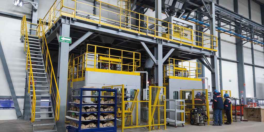
The successful implementation of these processes for steel castings underscores the importance of moving beyond static geometric rules to a dynamic understanding of heat transfer during solidification.
2. Comprehensive Process Control Measures
Beyond process design, meticulous control of various parameters is crucial for producing high-integrity steel castings.
2.1 Control of Pouring Temperature
Pouring temperature significantly impacts shrinkage behavior. Excessively high temperatures increase liquid shrinkage, demanding more feed metal from risers and potentially leading to shrinkage cavities if the riser volume is insufficient. Excessively low temperatures risk cold shuts and misruns. An optimal range must be maintained based on the weight of the steel casting. The following table provides a guideline:
| Weight of Steel Casting (kg) | Recommended Pouring Temperature (°C) |
|---|---|
| ≤ 500 | 1580 – 1600 |
| ≤ 3000 | 1570 – 1590 |
| ≤ 10000 | 1560 – 1580 |
| ≤ 25000 | 1550 – 1580 |
This relationship can be modeled empirically. For a steel casting of mass \( m \), an approximate optimal pouring temperature \( T_p \) can be estimated as:
$$ T_p = T_{\text{liquidus}} + \Delta T(m) $$
where \( T_{\text{liquidus}} \) is the liquidus temperature of the steel (e.g., ~1420°C for WCB) and \( \Delta T(m) \) is a superheat that decreases with increasing mass, as shown in the table.
2.2 Chemical Composition Control
The chemical composition of the steel directly influences its casting characteristics, including shrinkage behavior and hot tear susceptibility. For common carbon steel castings like WCB, strict control of elements is vital. The standard composition ranges and their impact are summarized below:
| Element | Specification Limit (WCB, wt.%) | Influence on Defects in Steel Castings | Optimal Control Range (Suggested) |
|---|---|---|---|
| Carbon (C) | ≤ 0.30 | High C increases fluidity but also shrinkage and cracking tendency. Low C reduces strength. | 0.21 – 0.24% to minimize hot tearing. |
| Manganese (Mn) | ≤ 1.00 | Counteracts sulfur, improves strength and toughness. Reduces hot tearing. | Aim for upper limit (e.g., ~0.80-1.00%). |
| Silicon (Si) | ≤ 0.60 | Deoxidizer. Moderate levels can reduce hot tear tendency. | ~0.40% |
| Phosphorus (P) | ≤ 0.04 | Harmful. Increases cold brittleness and cold cracking risk. | < 0.025% |
| Sulfur (S) | ≤ 0.045 | Harmful. Forms low-melting-point sulfides, promoting hot tearing. | < 0.025% |
The combined effect of S and P on cracking can be qualitatively assessed. Keeping their sum low is critical for sound steel castings:
$$ [P] + [S] < 0.05\% \text{ (for high-quality steel castings)} $$
where [P] and [S] are weight percentages.
2.3 Mold and Core Material Selection
The mold material’s properties, especially its collapsibility (yield) after the steel casting solidifies, are paramount for preventing cracks, particularly in complex, restrained geometries like valve bodies. While green sand or sodium silicate-bonded sand offer better collapsibility, environmental and surface finish concerns have shifted the industry towards resin sands. However, some resin systems produce high-strength molds with poor yield.
Based on my experience, for steel castings like butterfly valves, using an ester-cured alkaline phenolic resin self-setting sand is advantageous. It offers a good balance of strength, surface finish, and, importantly, superior high-temperature collapsibility. Typical additions are 1.5–2.5% resin and 20–30% catalyst (relative to resin weight). Furthermore, adding 2–3% wood flour or other breakdown agents to the sand mix enhances collapsibility. For large cores, designing them as hollow or embedding polystyrene foam blocks in the backing sand can significantly reduce mold resistance to contraction, thereby lowering stress in the solidified steel casting.
2.4 Gating System and Auxiliary Techniques
Ingates should be positioned to avoid direct impingement on cores or hot spots. A distributed gating system helps achieve uniform filling and reduces thermal gradients. The use of chills is highly effective in eliminating isolated hot spots in steel castings. By accelerating solidification at a hot spot, a chill effectively reduces its effective modulus \( (V/A) \), aligning its solidification time with the feeding system. The chill size can be approximated based on the modulus of the hot spot it needs to control.
Riser efficiency can be enhanced using exothermic or insulating sleeves, or by employing pressure-fed risers (e.g., atmospheric risers). Pouring additional hot metal into open risers during the final stage of pouring is another practical method to improve feeding for steel castings.
2.5 Cooling and Shakeout Control
Premature shakeout (removal from the mold) is a common cause of cold cracks in steel castings due to the introduction of rapid, non-uniform cooling and high thermal stress. Steel castings should be allowed to cool in the mold to a temperature where the risk of high internal stress is minimized, typically between 250°C and 450°C. The required holding time \( t_h \) in the mold can be estimated based on the dominant wall thickness \( d \) of the steel casting and is often represented by empirical curves. A simplified correlation for medium-sized carbon steel castings is:
$$ t_h \approx C \cdot d^2 $$
where \( C \) is a constant depending on mold material and casting geometry (e.g., ~0.5 to 2.0 hour/cm²). The following data provides a general guideline:
| Description of Steel Casting Section | Approximate Cooling Time in Mold (hours) | Typical Dominant Wall Thickness (mm) |
|---|---|---|
| Most walls < 35mm, with local heavier sections | 4 – 10 | 25 – 35 |
| Most walls 36 – 80mm, with local heavier sections | 10 – 24 | 50 – 80 |
| Most walls 81 – 200mm, with local heavier sections | 24 – 72 | 100 – 150 |
After shakeout, stress-relief annealing is highly recommended for complex steel castings like valve bodies to eliminate residual stresses and prevent service failures.
3. Defect Prevention Summary Table
The following table consolidates the primary defects in steel castings for butterfly valves, their root causes, and the corresponding preventive measures discussed.
| Defect Type | Primary Root Causes in Steel Castings | Key Preventive Measures |
|---|---|---|
| Shrinkage Cavities/Porosity | Insufficient feeding during liquid/solidification shrinkage; Poor riser design/location; High pouring temperature; Inadequate use of chills. | 1. Apply dynamic directional solidification principles. 2. Use simulation software for riser/chill design validation. 3. Optimize pouring temperature per casting weight. 4. Employ efficient risers (insulating/exothermic) and strategic chills. 5. Ensure proper gating to promote favorable temperature gradients. |
| Hot Tears/Cracks | Restricted contraction during solidification; Poor mold/core collapsibility; High S/P content; Sharp corners and large section changes; High thermal gradients. | 1. Improve mold/core collapsibility (e.g., ester-cured phenolic resin with breakdown agents). 2. Strictly control S and P levels (<0.025% each). 3. Optimize C, Mn, Si within suggested ranges. 4. Design with generous fillet radii; avoid abrupt thickness changes. 5. Use distributed gating, avoid ingates at hot spots. 6. Consider moderate to fast pouring rates to reduce thermal differentials. |
| Cold Cracks | High residual stress from non-uniform cooling; Premature shakeout; Complex geometry with restraint. | 1. Control shakeout temperature (250-450°C). 2. Perform stress-relief annealing after shakeout. 3. Optimize casting geometry and process to minimize stress concentration. |
4. Concluding Remarks
The production of high-quality steel castings for critical applications like butterfly valves is a complex interplay of design, material science, and process engineering. From my extensive involvement in this field, I assert that a holistic approach is non-negotiable. Simply relying on traditional rules-of-thumb is insufficient for today’s demands for reliability and cost-effectiveness. The adoption of dynamic solidification principles, empowered by modern simulation tools, provides a scientific basis for designing efficient and robust gating and risering systems for steel castings. This must be coupled with rigorous metallurgical control—particularly of harmful elements like sulfur and phosphorus—and the selection of mold materials that balance strength with collapsibility. Furthermore, disciplined process control regarding pouring temperatures and cooling regimes forms the final layer of defense against defects.
Steel castings will continue to be fundamental components in industry. By integrating theoretical understanding with practical insights and advanced validation techniques, manufacturers can significantly reduce the incidence of shrinkage and cracking defects. This leads not only to lower scrap rates and higher yields but also to more reliable and durable valve products in service. The journey towards perfecting steel castings is continuous, demanding constant learning, adaptation, and application of integrated solutions.